1978 Ford Bronco Heater Control Cable Routing Diagram - Installation & View A

Reference · 1978-1979 BroncoAll 44 schematics
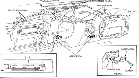
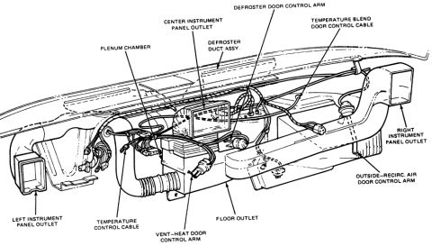
Routing diagram of heater control cables behind the instrument panel with the temperature control lever panel and cable assembly detail.
Part of 1978-1979 Ford Bronco Schematics
This document is a line-art schematic (exploded/installation illustration) showing the routing and attachment of heater control cables behind the instrument panel, uploaded as applying to a 1978 Ford Bronco. The main drawing depicts the dashboard from behind, with callouts identifying the INSTRUMENT PANEL, HEATER ASSY., and AIR DUCT. Cables are shown running from the heater control head across the back of the dash, with instructions to "ROUTE AS SHOWN" and secure with "TAPE." Two cable attachment points on the heater/plenum assembly are labeled "SEE VIEW A." A lower-left inset shows the heater control face with its levers: a fan lever marked HIGH/OFF, and slider legends reading FAN, COOL, TEMPERATURE, WARM on one row and OFF, HEAT, DEFROST on another. The lower-right inset, labeled VIEW A, details the cable end attachment hardware, identifying the CABLE ASSY., SPRING NUT, and SCREW used to fasten the cable to its bracket. A reader can learn how the heater temperature and function cables are routed, taped, and mechanically secured at the heater assembly, and what hardware (spring nut and screw) retains the cable ends. No part numbers, torque specs, or year/model text appear in the drawing itself.
Is this accurate? Sign in to help verify it.
Frequently asked questions
- How are the heater control cables secured behind the dash?
- The diagram instructs to route the cables as shown and secure them with tape along the instrument panel; at the heater assembly the cable ends are fastened per View A.
- What hardware attaches the heater cable to the heater assembly?
- View A shows the cable assembly is retained by a spring nut and a screw at the mounting bracket.
- What positions are shown on the heater control panel?
- The control face shows a fan lever with HIGH and OFF, plus slider legends for FAN, COOL, TEMPERATURE, WARM, and OFF, HEAT, DEFROST.
- Where do the heater cables connect on the heater assembly?
- Two attachment brackets on the heater assembly are called out as 'SEE VIEW A,' where each cable is secured with a spring nut and screw.
No comments yet.