Ford Bronco/F-Series 1992-96 Power Mirror Wiring Diagram - Switch & Wire Colors

Reference · 1987-1991 BroncoAll 175 wiring diagrams
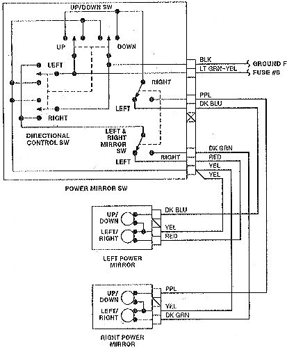

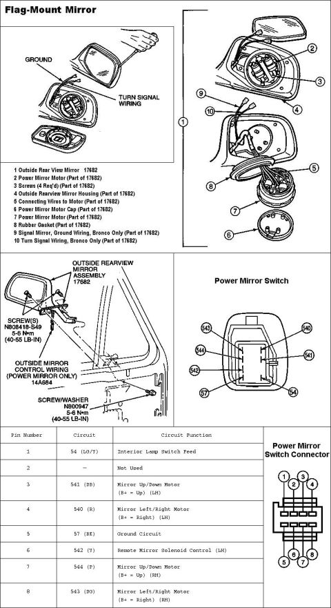
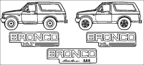





Wiring diagram of a power mirror switch circuit showing the directional control switch, mirror motors and color-coded wires.
Part of 1987-1991 Ford Bronco Wiring Diagrams
This document is a wiring diagram for a Ford power mirror system, uploaded as applicable to 1992-96 vehicles (per the filename) and filed under a 1990 Ford Bronco. It shows the internal switching logic of the power mirror switch assembly, which contains an up/down switch, a directional control switch (up, down, left, right positions), and a left & right mirror selector switch. The diagram traces eight wires leaving the switch: a black (BLK) wire to ground, a light green-yellow (LT GRN-YEL) wire to fuse #8, purple (PPL) and dark blue (DK BLU) wires, and dark green (DK GRN), red (RED), and two yellow (YEL) wires. The left power mirror motor assembly (with up/down and left/right motors) connects via dark blue, yellow, and red wires, while the right power mirror connects via purple, yellow, and dark green wires. A reader can use this diagram to identify which wire colors control each mirror's vertical and horizontal movement, locate the power feed (fuse #8) and ground for the switch, and diagnose problems such as a mirror that fails to move in one direction or on one side.
Applies to: not confirmed. The document shows Ford power mirror switch and mirror wiring; no year or model printed on it confirms a vehicle. It was uploaded under a 1990 Ford Bronco. Check the year and model on your own diagram before relying on it.
Reviewed by the SuperMotors Editorial Team · Spotted an error? Suggest a correction
Is this accurate? Sign in to help verify it.
Frequently asked questions
- What fuse powers the power mirror switch?
- The diagram shows the light green-yellow (LT GRN-YEL) wire from the power mirror switch going to Fuse #8.
- What wire colors go to the left power mirror?
- The left power mirror connects with dark blue (DK BLU), yellow (YEL), and red (RED) wires.
- What wire colors go to the right power mirror?
- The right power mirror connects with purple (PPL), yellow (YEL), and dark green (DK GRN) wires.
- How is the power mirror switch grounded?
- A black (BLK) wire from the power mirror switch goes to ground.
- What switches make up the power mirror switch assembly?
- The assembly contains an up/down switch, a directional control switch (up, down, left, right), and a left & right mirror selector switch.






No comments yet.