Ford Bronco Flag-Mount Power Mirror Diagram - Parts, Switch Wiring & Pinout

Reference · 1987-1991 BroncoAll 64 exploded parts diagrams
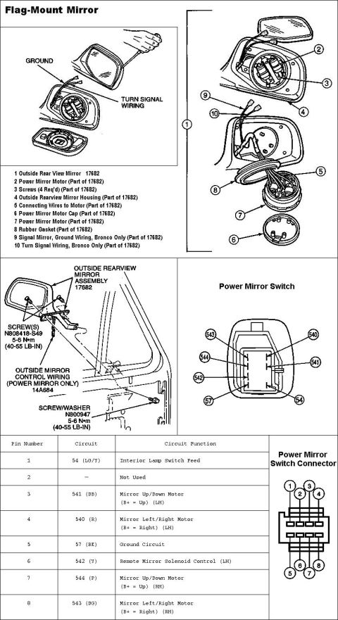

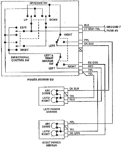






Outside power/flag-mount mirror exploded view (assembly 17682) with mirror switch connector pinout and circuits (up/down motor, left/right motor, ground); mounting screws torqued 4.5-6 N-m (40-55 lb-in).
Part of 1987-1991 Ford Bronco Exploded Parts Diagrams
This document is a Ford service reference page for the flag-mount exterior mirror, covering both the exploded parts breakdown and the power mirror switch wiring. The top section shows an exploded view of the outside rear view mirror assembly (base part number 17682), with a 10-item legend identifying the power mirror motor, screws (4 required), mirror housing, connecting wires, motor cap, rubber gasket, and, noted as 'Bronco Only', signal mirror ground wiring and turn signal wiring. A mounting diagram identifies the mirror assembly (17682), mounting screws N808418-S49 and screw/washer N800947 (both torqued to 5-6 N•m / 40-55 lb-in), and the outside mirror control wiring harness 14A684 (power mirror only). The right side shows the power mirror switch with circuit numbers (54, 57, 540, 541, 542, 543, 544) and an 8-pin connector pinout table listing each pin's circuit number, wire color, and function: interior lamp switch feed (54 LG/Y), LH mirror up/down (541 DB), LH left/right (540 R), ground (57 BK), remote mirror solenoid control (542 Y), RH up/down (544 P), and RH left/right (543 DG). Pin 2 is not used. A connector face diagram shows physical pin positions. Useful for mirror replacement, wiring diagnosis, and switch testing.
Is this accurate? Sign in to help verify it.
Frequently asked questions
- What is the part number for the Ford flag-mount outside rearview mirror assembly?
- The outside rearview mirror assembly is base part number 17682; the power mirror motor, screws, housing, gasket, and wiring are all listed as 'Part of 17682'.
- What torque is specified for the mirror mounting screws?
- Both the mounting screws (N808418-S49) and the screw/washer (N800947) are torqued to 5-6 N•m (40-55 lb-in).
- What are the power mirror switch connector pin assignments?
- Pin 1: circuit 54 (LG/Y) interior lamp switch feed; Pin 2: not used; Pin 3: 541 (DB) LH mirror up/down motor (B+ = Up); Pin 4: 540 (R) LH left/right motor (B+ = Right); Pin 5: 57 (BK) ground; Pin 6: 542 (Y) remote mirror solenoid control (LH); Pin 7: 544 (P) RH up/down motor (B+ = Up); Pin 8: 543 (DG) RH left/right motor (B+ = Right).
- Which wiring on the flag-mount mirror is Bronco-only?
- Items 9 and 10 in the legend, the signal mirror ground wiring and the turn signal wiring, are marked 'Bronco Only' (both part of 17682).
- What is the part number for the power mirror control wiring harness?
- The outside mirror control wiring (power mirror only) is part number 14A684.






No comments yet.