Home/
Registry/
Ford/
Bronco/
1987-1991/
1989 Ford Bronco/
Photo
supermotors.net/registry/media/431981
1989 Ford Bronco Brake Line Routing Sketch - Master Cylinder to Calipers & Rear

Reference · 1987-1991 BroncoAll 110 schematics
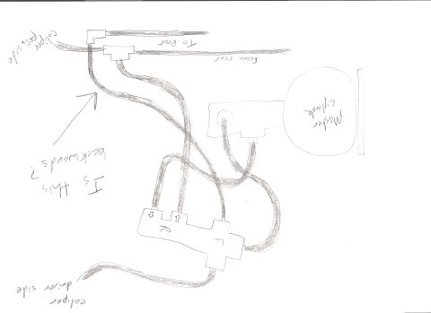
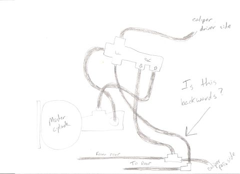





Hand-drawn schematic of brake hydraulic line routing between master cylinder, proportioning valve and calipers.
Part of 1987-1991 Ford Bronco Schematics
This document is a hand-drawn pencil sketch (not a factory schematic) of a vehicle's hydraulic brake plumbing layout, uploaded to a 1989 Ford Bronco gallery under the filename BRAKES.jpg. It shows a master cylinder feeding a combination/proportioning valve block, which is drawn with small directional arrow marks on its ports. From the valve, brake lines route to the driver-side front caliper (labeled "caliper driver side") and the passenger-side front caliper (labeled "caliper pass. side"). Additional lines run to a tee fitting at the bottom of the drawing where lines annotated "from rear" and "To Rear" connect, representing the rear brake circuit. The sketch includes a handwritten question, "Is this backwards?", with an arrow pointing at one of the lines between the valve and the lower tee fitting, indicating the author was troubleshooting or verifying correct brake line routing. There are no part numbers, torque specifications, year/model statements, or other technical data in the document. A reader can learn only the general intended routing of the brake lines as understood (and questioned) by the sketch's author; it documents a real owner's uncertainty about whether a particular line connection may be reversed.
Is this accurate? Sign in to help verify it.
Frequently asked questions
- What components are shown in this brake diagram?
- A master cylinder, a valve block (with directional arrow marks on its ports), lines to the driver-side and passenger-side calipers, and a tee fitting connecting lines labeled 'from rear' and 'To Rear'.
- What question is the author asking in the sketch?
- The note 'Is this backwards?' with an arrow points at a brake line running between the valve block and the lower tee fitting, questioning whether that connection is reversed.
- How do the front calipers connect in this sketch?
- One line from the valve block routes to the driver-side caliper, and another line routes down toward the passenger-side caliper near the bottom right of the drawing.
- Does this document give part numbers or torque specs?
- No. It is a hand-drawn routing sketch with only handwritten labels; it contains no part numbers, torque values, or specifications.






No comments yet.