Home/
Registry/
Ford/
Bronco/
1980-1986/
“THE DESTROYER”/
Photo
supermotors.net/registry/media/547921
1985 Ford F-Series & Bronco Wiring Diagram - Chassis Electrical, Fuse Box (6-69)
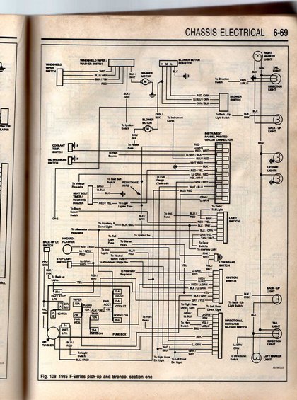
Manual wiring diagram of the 1985 Ford F-Series/Bronco chassis electrical system with color-coded circuits and connectors.
This is a scanned page (6-69) from a chassis electrical section of an automotive service manual, showing Figure 108: the wiring diagram for the 1985 Ford F-Series pickup and Bronco, section one. The diagram traces circuits for the windshield wiper/washer switch and motor, blower motor and resistor with blower switch (H-M-L), coolant temperature and oil pressure switches, seat belt timer/warning buzzer, instrument panel printed circuit connector (with wire colors such as RED, LT.GRN, RED/WHT, BLU/RED, WHT/RED, RED/YEL, GRN/WHT), the light switch, ignition switch, stop light switch, back-up light switch, hazard and directional flashers, low brake switch, and the directional/horn/hazard switch. Exterior lighting circuits include right and left marker lights, tail lights, direction lights, back-up lights, and license lights. A fuse box legend lists positions and ratings: HAZ/STOP LTS 20A, WIPER 10A, RADIO 10A, AUX FUEL TANK 10A, PWR WDS CB, HEATER CB, INST LTS 5A, EMISSION 15A, TAIL LT 15A, PWR ACCY CB, CTSY LT 15A, and HORN/CIG 20A. Wire color codes are labeled throughout, making this useful for tracing chassis electrical circuits on 1985 F-Series and Bronco trucks (and closely related model years).
Is this accurate? Sign in to help verify it.
Frequently asked questions
- What vehicles does this wiring diagram cover?
- The figure caption states 'Fig. 108 1985 F-Series pick-up and Bronco, section one,' from the Chassis Electrical section (page 6-69).
- What fuse ratings are shown in the fuse box on this diagram?
- HAZ/STOP LTS 20A, WIPER 10A, RADIO 10A, AUX FUEL TANK 10A, INST LTS 5A, EMISSION 15A, TAIL LT 15A, CTSY LT 15A, HORN/CIG 20A, plus circuit breakers (CB) for HEATER, PWR WDS, and PWR ACCY.
- What wire colors go to the blower switch?
- The blower switch is shown with RED/ORN, LT.BLU/ORN, and ORN/BLK wires, with BLK from the blower motor resistor and ORN/BLK feeding the blower motor.
- What wire colors connect to the light switch?
- The light switch shows BLU/RED (to instrument fuse), BRN, RED/YEL, BLK/PNK, BLK/ORN, GRN/YEL, and TAN/WHT, with connections to park/tail lights, door switches, and the courtesy light.
- Which circuits are included in this 'section one' diagram?
- Windshield wiper/washer, washer motor, blower motor and resistor, coolant temp and oil pressure switches, seat belt timer/warning buzzer, instrument panel printed circuit connector, light switch, ignition switch, stop light and back-up light switches, hazard and directional flashers, low brake switch, directional/horn/hazard switch, fuse box, and exterior marker, tail, direction, back-up, and license lights.
Comments
More from this build








No comments yet.