Home/
Registry/
Ford/
Bronco/
1980-1986/
“THE DESTROYER”/
Photo
supermotors.net/registry/media/547922
1985 Ford F-Series & Bronco Wiring Diagram - EEC, Lighting, Alternator (Fig 109)
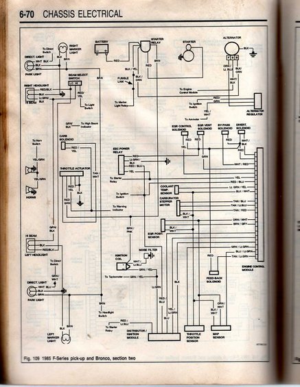
Manual wiring diagram of the 1985 Ford F-Series/Bronco engine and charging circuits with color-coded wires.
This is a scanned page (6-70, Chassis Electrical) from an automotive service manual showing Figure 109, a wiring diagram labeled '1985 F-Series pick-up and Bronco, section two.' The schematic covers the front lighting and engine-control wiring: battery, starter and starter relay, alternator (with F/S/B terminals) and alternator regulator, fusible link, right and left headlights, marker lights, park/direction lights, beam select (lo/hi) switch, horns, carb solenoid, throttle actuator, EEC power relay, EGR control/vent solenoids, by-pass and diverter solenoids, coolant temperature sensor, carburetor stepper motor, EGR position sensor, ignition coil with noise filter, feed-back solenoid, distributor/ignition module, throttle position sensor, MAP sensor, and the Engine Control Module connector. Wire color codes are given throughout (e.g., RED/GRN to the alternator regulator, GRN/BLK to the high beam indicator, TAN/BLU and TAN/RED to the carburetor stepper motor, ORN/WHT and BLK/WHT to the throttle position sensor). Cross-references indicate connections to the ignition switch, light switch, ammeter, warning indicator, tachometer, headlight switch, and marker light relay. Useful for tracing feedback-carbureted EEC and lighting circuits on 1985 Ford F-Series trucks and Broncos.
Is this accurate? Sign in to help verify it.
Frequently asked questions
- What vehicles does this wiring diagram cover?
- The caption states 'Fig. 109 1985 F-Series pick-up and Bronco, section two,' so it covers 1985 Ford F-Series pickups and Broncos.
- What wire colors go to the throttle position sensor?
- The diagram shows ORN/WHT and BLK/WHT wires at the throttle position sensor.
- What color wire runs to the high beam indicator?
- A GRN/BLK wire from the beam select switch circuit goes to the high beam indicator.
- What components connect to the Engine Control Module in this diagram?
- Wires from the EEC power relay, EGR control/vent solenoids, by-pass and diverter solenoids, coolant temp sensor, carburetor stepper motor, EGR position sensor, ignition coil, feed-back solenoid, distributor/ignition module, throttle position sensor, and MAP sensor route to the Engine Control Module connector.
- What wire colors are at the carburetor stepper motor?
- TAN/BLU, TAN/Lt.BLU, TAN/RED, and BLK/WHT wires are shown at the carburetor stepper motor.
Comments
More from this build









No comments yet.