SuperMotors SuperMotors SUPERMOTORS Search: try “orange Bronco on 35s”
Home/ Registry/ Ford/ Bronco/ 1987-1991/ 1990 Ford Bronco/ Photo supermotors.net/registry/media/563298

110V/220V Split-Phase Wiring Diagram - Black, White & Red Wire Voltages

Electrical diagram of 110/220 volt split-phase with black, white and red conductors and voltage labels
Electrical diagram of 110/220 volt split-phase with black, white and red conductors and voltage labelsOriginal file
Electrical diagram of 110/220 volt split-phase with black, white and red conductors and voltage labels

Reference · 1987-1991 BroncoAll 175 wiring diagrams

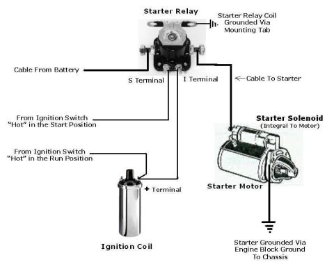
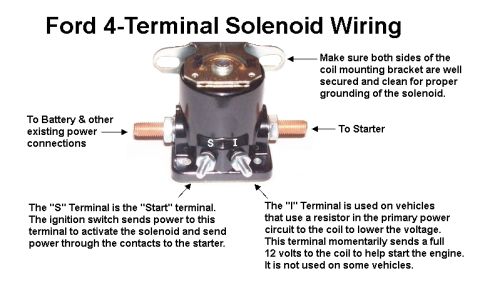
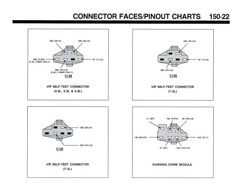
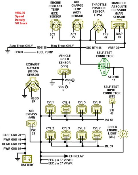
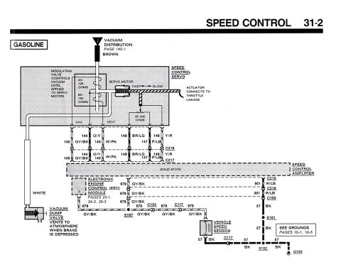
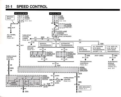
Ford Bronco RABS Module Harness Connector Pin View - Pin #2 Location Diagram Ford RABS Module Harness Connector Pin View Diagram - Pins 1 & 9 (1990 Bronco) 110V/220V Split-Phase Wiring Diagram - Black, White & Red Wire Voltages Ford 3G Alternator Wiring Diagram - Mega Fuse, Charge Lamp & Wire Colors 1973-1974 Ford Point-Type Ignition System Circuit Diagram - Coil & Distributor Ford 4-Terminal Starter Relay Wiring Diagram - S & I Terminals, Coil & Starter Ford 4-Terminal Starter Solenoid Wiring Diagram - S & I Terminal Functions KC Driving Lights & LED Light Bar Relay Wiring Diagram - Ford Bronco Aux Lights Connector faces page 150-22 with C128 VIP self-test connector pinouts and warning chime module 1986-95 Ford V8 Truck Speed Density EEC-IV Pinout Wiring Diagram 1990 Ford Bronco Speed Control Wiring Diagram 31-2 - Cruise Servo & Amplifier 1990 Ford Bronco Speed Control Wiring Diagram 31-1 - Cruise Control Circuit 175wiring diagrams1987-1991 Ford Bronco More reference Ford Bronco PCV System Airflow Diagram - Crankcase Ventilation Flow SchematicSchematic How to Find TDC for Distributor Installation - Ford Firing Order & Valve OverlapService procedure Ford Bronco 'America's Truck. Built Ford Tough.' print ad with red Bronco and feature sketchesBrochure Welder Input Data Plate - Serial JH229505, Stock 901782, 200/230/460V SpecsSpec plate Ford 5.0L V8 PCV Valve & Hose Routing Diagram - 9A474, 6B890, 6A664Exploded parts Ford 5.0L/5.8L Air Throttle Body Assembly Diagram - Canister Purge Ports & TPSManual page Tubing Adapter Blueprint 2.00" OD x 1.375" ID x 3" - 1.125"-12 TPI RH ThreadBlueprint '89 Ford vehicle emission control information label with EEC IV/EFI timing steps and vacuum hose routingVacuum routing 1990 Ford Bronco Fuse Panel Diagram: Fuse Positions, Amps & Circuits (11-2)Fuse chart Ford V8 Intake Manifold Bolt Tightening Sequence Diagram - Stud LocationsTorque spec

Electrical diagram showing 110V and 220V split-phase relationships across color-coded Black, White and Red conductors.

Part of 1987-1991 Ford Bronco Wiring Diagrams

AI caption · Photo 280 of 700

This document is a simple color diagram illustrating the voltage relationships in a split-phase electrical system using three conductors. Three horizontal bars represent the wires: a black bar labeled "110+ Black" at the top, a white bar labeled "0 White" in the middle, and a red/orange bar labeled "110- Red" at the bottom. Double-headed arrows show the potential differences between conductors: 110 volts between the Black wire and the White (neutral) wire, 110 volts between the White wire and the Red wire, and 220 volts measured directly between the Black and Red wires. A reader can learn from this diagram that two 110-volt legs of opposite polarity relative to a common neutral (White, at 0 volts) combine to provide 220 volts across the two hot legs (Black and Red), while either hot leg to neutral yields 110 volts. The diagram contains no vehicle-specific information, part numbers, fuse data, or connector details; it is a general electrical reference showing how 110V and 220V are derived from the same three-wire system. It was uploaded to a 1990 Ford Bronco gallery but is generic electrical reference material rather than automotive wiring.

Is this accurate? Sign in to help verify it.

Frequently asked questions

What voltage is between the black and white wires?
110 volts, as shown by the arrow between the Black (110+) wire and the White (0) wire.
What voltage is between the black and red wires?
220 volts, shown by the long arrow spanning from the Black (110+) wire to the Red (110-) wire.
Which wire is the neutral (0 volt) conductor in this diagram?
The White wire, labeled "0 White," sits at 0 volts between the two 110-volt legs.
How is 220 volts obtained from two 110-volt lines?
By measuring across the two opposite hot legs, Black (110+) and Red (110-), which together yield 220 volts, while each measures 110 volts to the White neutral.


Comments

No comments yet.

More 1987-1991 Broncos