Home/
Registry/
Ford/
Bronco/
1978-1979/
1978 Ford Bronco/
Photo
supermotors.net/registry/media/578817
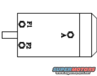
Winch Motor Terminal Diagram - F1, F2 & A Post Locations (Ford Bronco Winch)
Reference · 1978-1979 BroncoAll 44 schematics









Simple terminal schematic of a motor/alternator end showing F1, F2 and A connection points.
Part of 1978-1979 Ford Bronco Schematics
This document is a simple line-drawing schematic showing the terminal layout of what appears to be a winch motor, uploaded to the gallery of a 1978 Ford Bronco under the filename "winch diagram.jpg." The drawing depicts a rectangular motor body with a small protruding tab or shaft on one end. Three threaded terminal studs are shown and labeled: two field terminals marked "F1" and "F2" positioned on the end of the body nearest the protrusion, and a single armature terminal marked "A" positioned toward the middle/opposite end of the housing. No wire colors, part numbers, torque specifications, amperage ratings, model years, or manufacturer names appear anywhere in the image. A reader can learn from this diagram which physical stud on the motor corresponds to each electrical terminal designation (F1, F2, and A), which is useful when wiring or rewiring a winch motor and solenoid pack, since correct identification of the field and armature terminals is necessary for proper in/out operation. Beyond terminal identification and relative placement, the document contains no additional textual or tabular information.
Is this accurate? Sign in to help verify it.
Frequently asked questions
- What terminals are shown on this winch motor diagram?
- Three terminals are labeled: F1, F2, and A.
- Where are the F1 and F2 terminals located on the motor?
- F1 and F2 are the two terminal posts on the same end of the motor body, near the protruding tab/shaft, with F1 above F2 as drawn.
- Where is the A terminal located?
- The A terminal is a single post located toward the middle/opposite end of the motor body, away from F1 and F2.
- Does the diagram include wire colors or part numbers?
- No. The only text visible in the document is the three terminal labels F1, F2, and A.






No comments yet.