SuperMotors SuperMotors SUPERMOTORS Search: try “orange Bronco on 35s”
Home/ Registry/ Ford/ Bronco/ 1987-1991/ 1991 Ford Bronco/ Photo supermotors.net/registry/media/591256

Intake and exhaust flow table at 28" H2O for GT-40P, GT-40, E7TE…
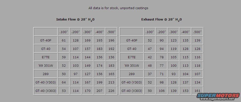
Intake and exhaust flow table at 28" H2O for GT-40P, GT-40, E7TE, '69 351W and 289 cylinder heads
Intake and exhaust flow table at 28" H2O for GT-40P, GT-40, E7TE, '69 351W and 289 cylinder headsOriginal file
Intake and exhaust flow table at 28" H2O for GT-40P, GT-40, E7TE, '69 351W and 289 cylinder heads

Reference · 1987-1991 BroncoAll 54 manual pages
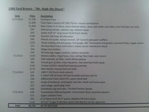
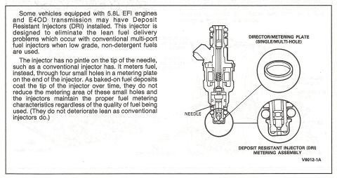
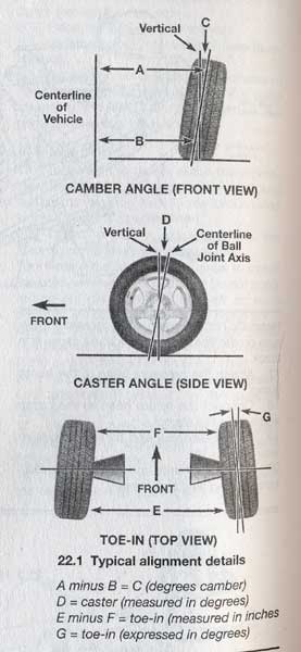
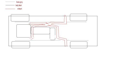
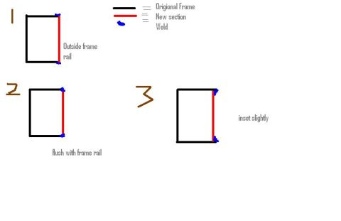
Intake and exhaust flow table at 28" H2O for GT-40P, GT-40, E7TE, '69 351W and 289 cylinder heads Ford 5.0L/5.8L Air Throttle Body Assembly Diagram - Canister Purge Ports & TPS Ford 5.0L/5.8L EFI Air Throttle Body Assembly Diagram - TPS & Air Bypass Valve 1988 Ford Bronco Build Cost Sheet - "Mr. Hyde the Deuce" Parts & Expense List 1990 Ford Bronco/F-Series Oil Pressure Gauge Specs & Sender Location 33-32-4 1990 Ford Bronco Instrument Cluster Circuit Operation & Sender Specs (60-7) Ford 5.8L EFI Deposit Resistant Injector (DRI) Diagram & Description - E4OD 1990 Ford Bronco Horn & Cigar Lighter Circuit (EVTM 44-2) - Locations & Operation Dana 60 Monobeam Axle Lower Kingpin Removal Diagram - Ford Two-Jaw Puller Dana 60 Monobeam Front Axle Lower Kingpin Removal Diagram - Fig. 102 Dana 60 Monobeam Front Axle Compression Spring Removal Diagram (Fig. 101) Wheel Alignment Basics Diagram - Camber, Caster & Toe-In Explained (Ford Bronco) 54manual pages1987-1991 Ford Bronco More reference 1991 Ford Bronco Dual Exhaust Routing Diagram - Underside Layout SketchSchematic Frame Rail Section Weld Placement Diagram - Outside, Flush & Inset Splice OptionsService procedure Tubing Adapter Blueprint 2.00" OD x 1.375" ID x 3" - 1.125"-12 TPI RH ThreadBlueprint Ford 3G Alternator Wiring Diagram - Mega Fuse, Charge Lamp & Wire ColorsWiring diagram Welder Input Data Plate - Serial JH229505, Stock 901782, 200/230/460V SpecsSpec plate Ford 5.0L V8 PCV Valve & Hose Routing Diagram - 9A474, 6B890, 6A664Exploded parts Magnum Metropolitan Brochure - Ford Bronco/F-Series Suburban-Style ConversionBrochure Ford Thermactor Combination Valve Diagram - Air Bypass/Control Ports LabeledVacuum routing 1990 Ford Bronco Fuse Panel Diagram: Fuse Positions, Amps & Circuits (11-2)Fuse chart Ford V8 Intake Manifold Bolt Tightening Sequence Diagram - Stud LocationsTorque spec

Flow data for stock, unported GT-40P, GT-40, E7TE, '69 351W, 289 and GT-40 (Y303/X303) heads at .100" to .500" lift, 28" H2O.

Part of 1987-1991 Ford Bronco Manual Pages

AI caption · Photo 293 of 420

AH data 5 far stark unnamed Lastmgs Intakg Flaw 29" H2:- Exhaust Flaw 29" H2:- .1uu .2uu .Suu .4uu 599 .199 .299 .399 .499 .599 677499 51 129 159 195 195 977499 52 99 123 135 139 emu 54 107 157 193 192 GT74U 47 94 119 129 129 E7TE 59 114 144 155 155 E7TE 42 75 195 115 115 59 351w 52 193 149 174 193 59 351w 49 77 mm 113 119 299 59 97 127 155 155 259 37 71 93 194 197 cr4uxv3ua! 54 114 157 199 213 cmuwaua) 52 99 129 137 134 cr4uix393! 53 114 17m 207 225 cmuqua) 59 195 139 153 151

Is this accurate? Sign in to help verify it.

Comments

No comments yet.

More 1987-1991 Broncos