Home/
Registry/
Ford/
Bronco/
1987-1991/
1991 Ford Bronco/
Photo
supermotors.net/registry/media/612594
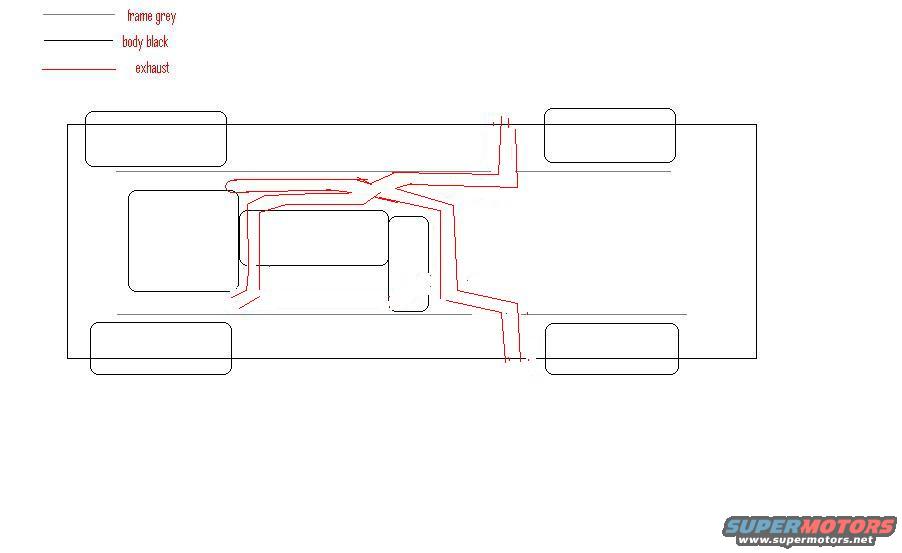
1991 Ford Bronco Dual Exhaust Routing Diagram - Underside Layout Sketch
Reference · 1987-1991 BroncoAll 112 schematics
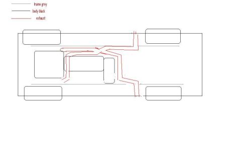











Top-down chassis schematic showing a crossover exhaust-routing layout, with a legend for frame, body and exhaust lines.
Part of 1987-1991 Ford Bronco Schematics
This document is a simple hand-drawn schematic (apparently made in a basic paint program) showing a proposed or existing dual exhaust routing on a vehicle, filed by the uploader under their 1991 Ford Bronco. The drawing is a top-down (underside) view of the vehicle: grey lines represent the frame, black lines represent the body outline (including four wheel/tire rectangles and center shapes representing the engine, transmission, and transfer case area), and red lines represent the exhaust routing. The red exhaust path runs from the engine area, with pipes from both sides of the engine converging near the transmission, then splitting and routing rearward along both sides of the driveline, exiting at both the front-passenger area and rear of the vehicle. The only text in the document is the three-item legend: 'frame grey', 'body black', and 'exhaust'. There are no part numbers, dimensions, pipe diameters, muffler locations labeled, or year/model applicability stated anywhere in the drawing. It is one of a set of related drawings in the same album (dual exhaust variants and a single exhaust version), useful mainly as a conceptual routing sketch for planning a dual exhaust system layout.
Is this accurate? Sign in to help verify it.
Frequently asked questions
- What do the line colors mean in this exhaust diagram?
- Per the legend: grey lines are the frame, black lines are the body, and red lines are the exhaust routing.
- What kind of exhaust setup does this diagram show?
- It shows a dual exhaust routing in red, with pipes coming from both sides of the engine, merging near the center, then splitting and running rearward to exits on both sides of the vehicle.
- Does the diagram include pipe sizes, part numbers, or muffler specifications?
- No. The only text in the document is the three-item color legend; no dimensions, part numbers, or component labels are shown.
- What perspective is the drawing shown from?
- It is a top-down/underside view of the vehicle showing the frame, body outline, four wheels, and the driveline area with the exhaust path traced in red.






No comments yet.