Home/
Registry/
Ford/
Bronco/
1987-1991/
1991 Ford Bronco/
Photo
supermotors.net/registry/media/586534
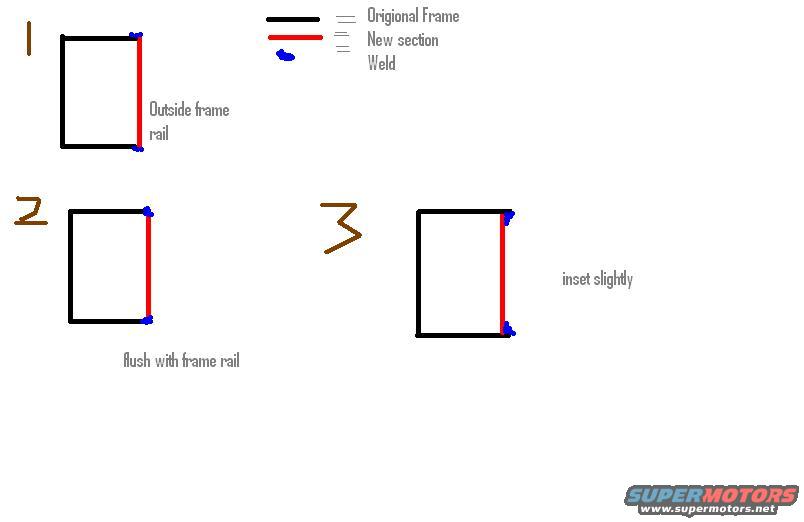
Frame Rail Section Weld Placement Diagram - Outside, Flush & Inset Splice Options
Reference · 1987-1991 BroncoAll 95 service procedures





Instructional diagram comparing three weld-placement options for splicing a new frame section to an original frame rail.
Part of 1987-1991 Ford Bronco Service Procedures
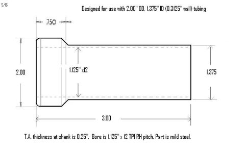
This is a simple hand-drawn illustration (not a factory document) showing three possible methods for welding a new section onto a vehicle frame rail. A color-coded legend defines the elements: black lines represent the original frame, red lines represent the new section being added, and blue marks represent weld locations. Diagram 1 shows the new section positioned on the outside of the frame rail, overlapping the original frame's edge, with welds at the top and bottom corners. Diagram 2 shows the new section mounted flush with the frame rail, butting up evenly against the original frame's end. Diagram 3 shows the new section inset slightly inside the original frame rail, again with welds at the top and bottom joints. The drawing was uploaded to a 1991 Ford Bronco gallery alongside other sketches of tubing adapters, suggesting it documents a planned or completed frame repair or modification. A reader can learn the three basic placement options for a frame rail splice section (outside overlap, flush butt, or slight inset) and where welds are placed in each configuration, though no dimensions, materials, weld specifications, or vehicle-specific applicability information is given.
Is this accurate? Sign in to help verify it.
Frequently asked questions
- What do the colors in this frame rail diagram mean?
- Black lines indicate the original frame, red lines indicate the new section, and blue marks indicate weld locations.
- What three ways of joining a new section to a frame rail are shown?
- 1) New section on the outside of the frame rail, 2) new section flush with the frame rail, and 3) new section inset slightly into the frame rail.
- Where are the welds placed in each configuration?
- In all three diagrams, welds (blue marks) are shown at the top and bottom of the joint where the red new section meets the black original frame.
- Does the diagram give dimensions or weld specifications?
- No. It only shows relative placement of the new section (outside, flush, or inset) and weld locations; no dimensions, materials, or weld specs are included.






No comments yet.