SuperMotors SuperMotors SUPERMOTORS Search: try “orange Bronco on 35s”
Home/ Registry/ Ford/ Bronco/ 1980-1986/ “Boss”/ Photo supermotors.net/registry/media/602746

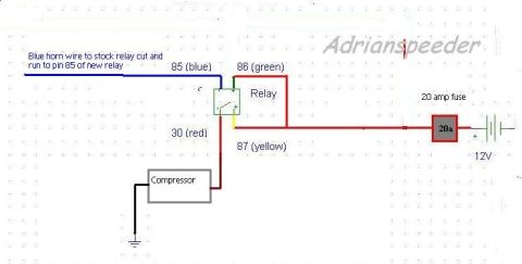
Ford Bronco Air Horn Compressor Relay Wiring Diagram - Pins 30/85/86/87, 20A Fuse
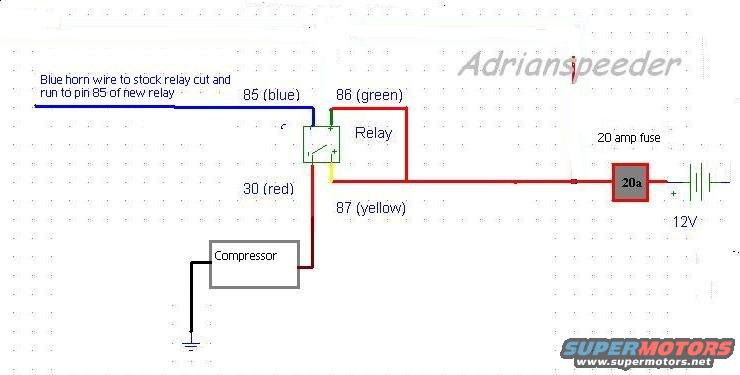
Horn relay wiring diagram with relay pins 85/86/87/30, fuse, compressor and 12V
Horn relay wiring diagram with relay pins 85/86/87/30, fuse, compressor and 12VOriginal file
Horn relay wiring diagram with relay pins 85/86/87/30, fuse, compressor and 12V

Reference · 1980-1986 BroncoAll 92 wiring diagrams
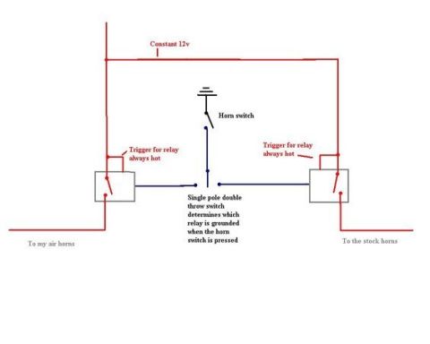
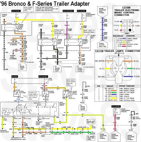
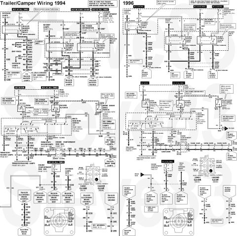
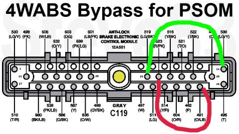
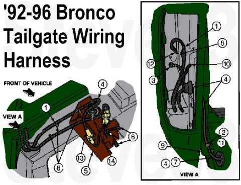
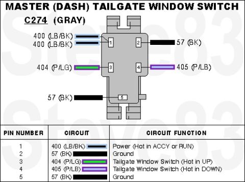
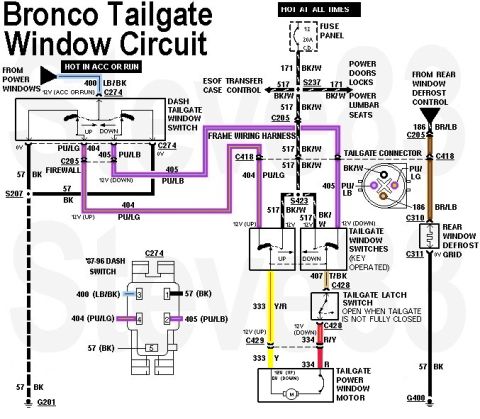
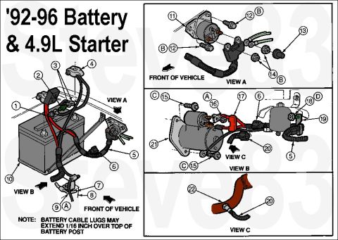
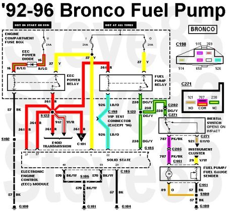
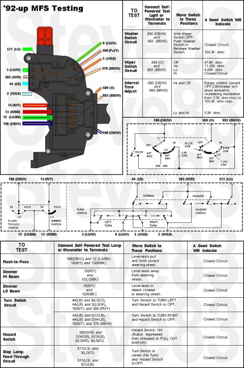
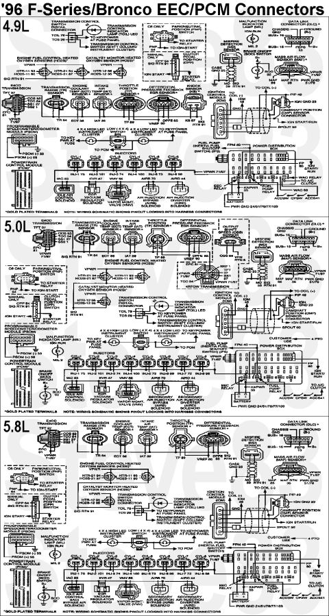
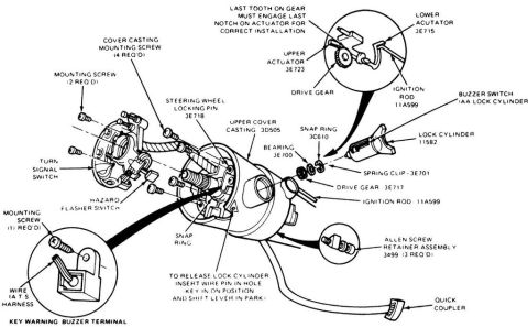
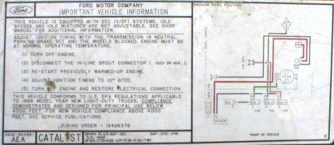
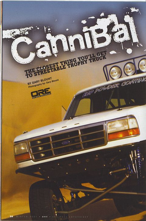
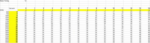
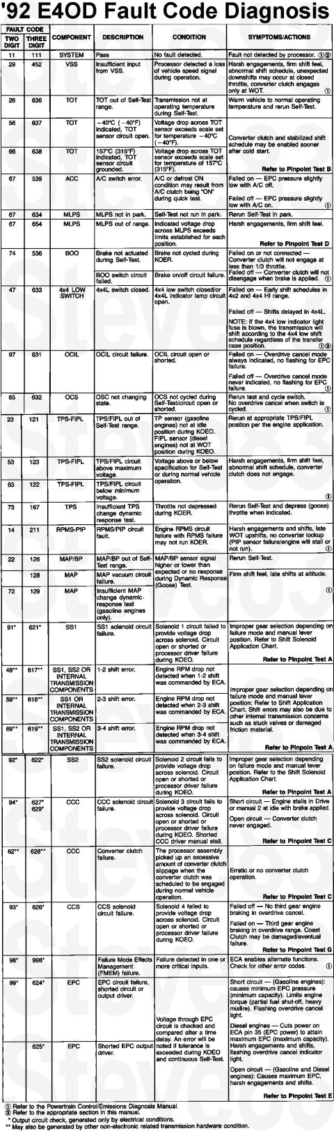
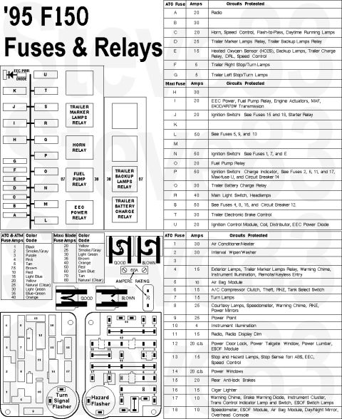
Dual Horn Wiring Diagram - Air Horns & Stock Horns with Relays & SPDT Switch Ford Bronco Air Horn Compressor Relay Wiring Diagram - Pins 30/85/86/87, 20A Fuse 1996 Ford Bronco & F-Series Trailer Wiring Diagram - 7-Pin Connector Pinout 1994 & 1996 Ford F-Series/Bronco Trailer Camper Wiring Diagram - Tow Package Ford 4WABS Bypass for PSOM - ABS Module Connector C119 Wiring Diagram 1992-1996 Ford Bronco Tailgate Wiring Harness Routing Diagram Ford Bronco Master Dash Tailgate Window Switch Wiring - C274 Connector Pinout Ford Bronco Tailgate Window Wiring Diagram - Circuit, Connectors & Wire Colors 1992-96 Ford 4.9L Battery & Starter Cable Routing Diagram (Bronco/F-Series) 1992-96 Ford Bronco Fuel Pump Wiring Diagram - Relay, Inertia Switch, EEC 1992-Up Ford Multifunction Switch (MFS) Testing - Terminal Pinout & Ohm Values 1996 Ford F-Series/Bronco EEC/PCM Connector Pinout Diagram: 4.9L 5.0L 5.8L 92wiring diagrams1980-1986 Ford Bronco More reference 1986 Ford Bronco Steering Column Exploded Diagram - Ignition Lock Cylinder PartsExploded parts '86 Ford EEC IV/EFI Important Vehicle Information decal with vacuum hose routing and timing stepsVacuum routing Off Road Enthusiast Cannibal feature opener with white Ford prerunner truck and roof lightsBrochure Ford Bronco Ignition Timing Curve Table - RPM vs Vacuum Advance (12° Base)Spec plate 1992 Ford E4OD Transmission Fault Code Diagnosis Chart - DTC List & SymptomsService procedure Smallblock V8 Coolant Flow Diagram - Ford Engine Cooling Path SchematicSchematic 1996 Ford Bronco/F-Series Starting System - Section 03-06 ContentsManual page Trim panel hole layout photos for positions A, B and C with tape measure readings from the body lineBlueprint Bronco drive shaft torque limits table and special tool T74P-4635-CTorque spec '95 F150 fuse and relay chart with fuse panel layout, ATC and Maxi fuse amp tablesFuse chart

Wiring diagram for an air horn compressor showing relay pins 85/86/87/30, a 20 amp fuse and 12V source with color-coded wires.

Part of 1980-1986 Ford Bronco Wiring Diagrams

AI caption · Photo 41 of 59

This document is a hand-drawn (computer-sketched) aftermarket horn/air compressor wiring diagram uploaded to a 1986 Ford Bronco gallery. It shows how to wire a new relay to control a compressor (likely for an air horn) using the vehicle's stock horn circuit as the trigger. The blue factory horn wire that ran to the stock relay is cut and re-routed to pin 85 of the new relay (shown in blue). Pin 86 (green wire) connects to the other relay coil terminal. Pin 30 (red wire) feeds the compressor, which is grounded on its other terminal (black wire to chassis ground symbol). Pin 87 (yellow wire) connects via a red power wire through a 20 amp fuse to the positive terminal of the 12V battery. The diagram identifies each relay pin by standard DIN numbering (85, 86, 30, 87) and by wire color, specifies the 20a fuse rating, and includes the watermark 'Adrianspeeder.' A reader can learn the complete circuit path for triggering an add-on compressor from the stock horn button using a standard 4-pin automotive relay, including which factory wire to intercept and what fuse size to use.

Is this accurate? Sign in to help verify it.

Frequently asked questions

Which relay pin does the stock horn wire connect to?
The blue horn wire to the stock relay is cut and run to pin 85 of the new relay.
What size fuse is used in this horn compressor circuit?
A 20 amp fuse is placed between pin 87 (yellow) and the positive terminal of the 12V battery.
What relay pin powers the compressor?
Pin 30 (red wire) connects to the compressor; the compressor's other terminal goes to ground.
What are the wire colors for each relay pin in this diagram?
Pin 85 is blue, pin 86 is green, pin 30 is red, and pin 87 is yellow.
What voltage does this circuit run on?
The circuit is powered by a 12V battery through the 20 amp fuse.
Comments

No comments yet.

More 1980-1986 Broncos