SuperMotors SuperMotors SUPERMOTORS Search: try “orange Bronco on 35s”
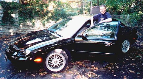
Home/ Registry/ Ford/ Taurus/ 1996-1999/ “My Baby”/ Photo supermotors.net/registry/media/65433

Ford Taurus Front ABS Sensor Ring Removal - Halfshaft CV Joint Tool 206-072

Service illustration showing front ABS sensor ring remover/replacer tool and driveshaft joint
Service illustration showing front ABS sensor ring remover/replacer tool and driveshaft jointOriginal file
Service illustration showing front ABS sensor ring remover/replacer tool and driveshaft joint

Reference · 1996-1999 TaurusAll 18 service procedures

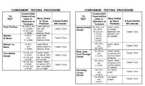
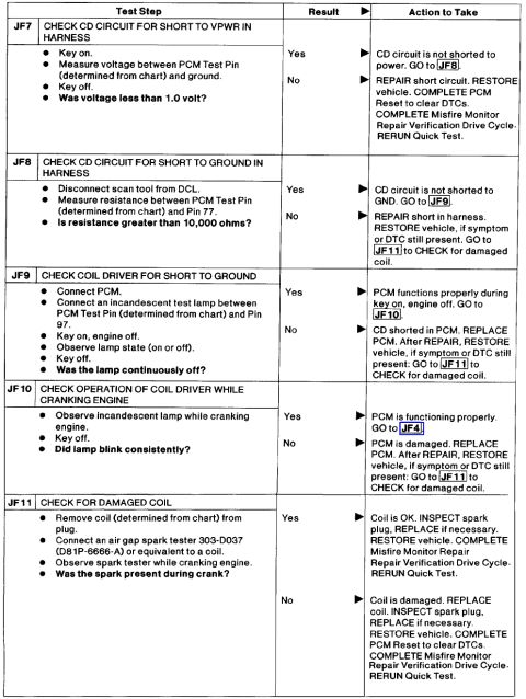
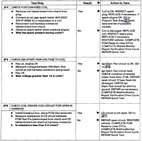
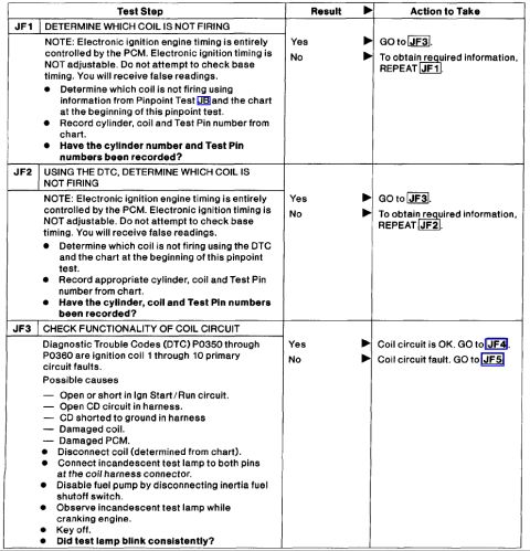
Ford Taurus Halfshaft ABS Sensor Ring Press Diagram: Tool 206-072 Ford Taurus Front ABS Sensor Ring Remover/Replacer 206-072 - Halfshaft Service Ford Taurus Halfshaft ABS Sensor Ring Press Install Diagram: Tool 206-072 Ford Taurus Front ABS Sensor Ring Removal - Halfshaft CV Joint Tool 206-072 Multi-function switch component testing tables with circuit numbers, wire colors and switch positions Ford Pinpoint Test JF7-JF11: Coil Driver (CD) Circuit & Ignition Coil Diagnosis Ford Pinpoint Test JF4-JF6: Ignition Coil & Coil Driver Circuit Misfire Diagnosis Ford Pinpoint Test JF1-JF3: Ignition Coil Not Firing Diagnosis (DTC P0350-P0360) Mercury Sable front air dam installation instructions with 12 steps and car drawings Ford AX4S Transaxle Pressure Test Port Locations Diagram - Line, EPC, Direct Clutch Ford Taurus Front Subframe Plate Nut Removal Diagram - Access Hole & Tab Ford Valve Shim Removal with Compressed Air - Tappet Holder T96P-6500-AH Diagram 18service procedures1996-1999 Ford Taurus More reference Starter Wire Bypass Switch Diagram - 12V Push-Button Starter Circuit (Ford Taurus)Wiring diagram 1998 Ford Taurus Halfshaft CV Joint & Boot Diagram - E6715-F Callout FigureExploded parts 2004 Ford SVT Mustang Cobra Mystichrome Edition display placard listing specs and featuresBrochure Engine coolant/intake air temperature sensor values table of temperature, voltage and resistanceManual page 1999 Ford Taurus SHO window sticker with equipment list, 16 city / 25 highway MPG and $29,550 MSRPSpec plate Ford Taurus SHO 3.4L V8 Serpentine Drive Belt Routing Diagram & Pulley GuideSchematic 1997 Ford Taurus Gen 3 Engine Compartment Fuse Box Diagram - Fuse & Relay ChartFuse chart V8 Prototype Intake Manifold Runner Horns Patent Drawing: Figure 8 Plenum LayoutBlueprint 1997 Ford Taurus EATC Vacuum Schematic - Hose Routing & Part NumbersVacuum routing

Service-procedure illustration showing the front-wheel driveshaft joint, ABS sensor indicator and sensor-ring remover tool.

Part of 1996-1999 Ford Taurus Service Procedures

AI caption · Photo 205 of 386

This document is a single illustration from a Ford service procedure showing the installation or removal of an anti-lock brake sensor ring (tone ring) on a front halfshaft. The line drawing depicts a hand holding the front wheel driveshaft joint (base part number 3B413) upside down over a bench-mounted Front Sensor Ring Remover/Replacer tool (tool number 206-072). An arrow points to the Front Brake Anti-Lock Sensor Indicator ring (base part number 2C182), the toothed ABS tone ring, positioned on the outer CV joint, ready to be pressed using the tool. The figure is identified by illustration code DE2184-A. From this page a reader can learn the correct special service tool (206-072) required to remove or replace the ABS sensor indicator ring from the front driveshaft joint, the relevant Ford base part numbers for the joint and the sensor ring, and the orientation of the joint in the tool during the operation. The page contains no torque specifications, year/model applicability statements, or step-by-step text; it appears to be one figure from a multi-page halfshaft service procedure set.

Is this accurate? Sign in to help verify it.

Frequently asked questions

What tool is used to remove or replace the front ABS sensor ring?
The Front Sensor Ring Remover/Replacer, tool number 206-072.
What is the part number of the front brake anti-lock sensor indicator ring?
The Front Brake Anti-Lock Sensor Indicator is base part number 2C182.
What part number identifies the front wheel driveshaft joint in this diagram?
The Front Wheel Driveshaft Joint is base part number 3B413.
How is the driveshaft joint positioned in the sensor ring tool?
The illustration shows the joint held by hand, splined shaft up, with the sensor indicator ring end lowered into the bench-mounted remover/replacer tool 206-072.

Comments

No comments yet.

More 1996-1999 Tauruss