1998 Ford Taurus/Sable Behind Dash Connector Locations - Air Bag Diagnostic Monitor C277

Reference · 1996-1999 TaurusAll 17 exploded parts diagrams


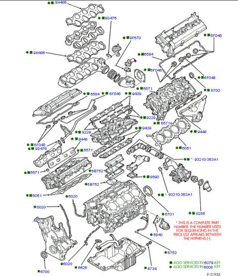
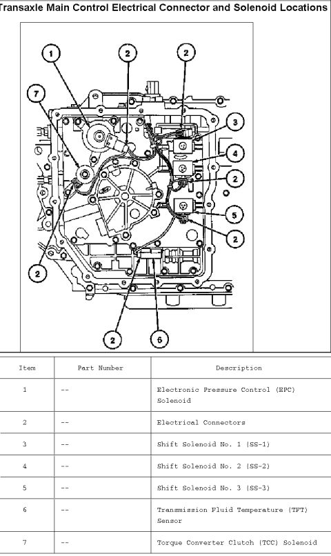
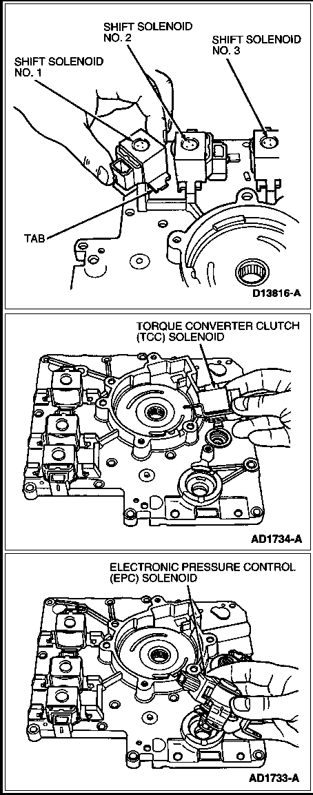


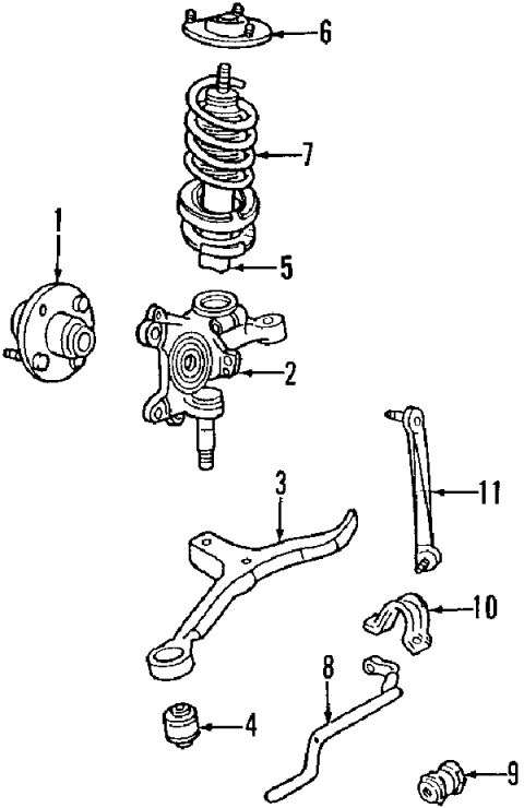
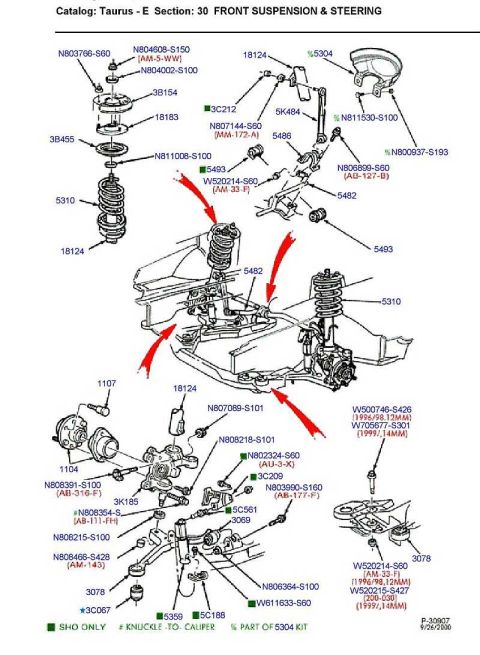


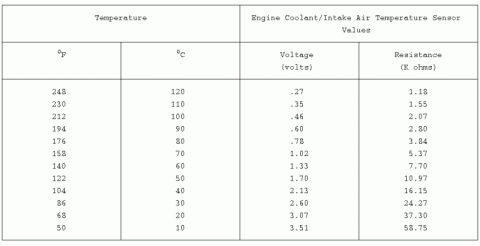

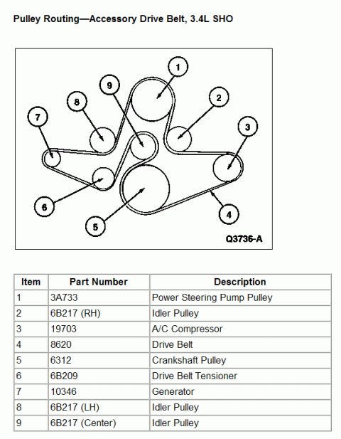
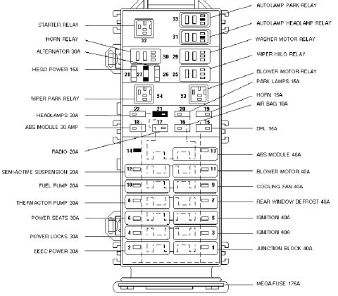
Component-location illustration of the instrument-panel harness with numbered connector callouts behind the dash.
Part of 1996-1999 Ford Taurus Exploded Parts Diagrams
This document is page 23 of 24 from a Ford Taurus/Sable factory wiring/connector location guide (document number FCS-12123-98), showing connector locations 'Behind I/P (1 of 2)', i.e., behind the instrument panel/dashboard. It is an exploded line drawing of the dash and its wiring harnesses overlaid with a lettered/numbered locator grid (columns 1-10, rows A-F). Callouts identify the physical location of numerous electrical connectors, including the sunload sensor (C2017), light sensor/amplifier (C2007), glove box switch/lamp (C2033), courtesy lamps (C2026, C2125), blower motor and speed controller (C215/C2043, C216/C233), passenger and driver air bags (C202, C:31), in-car temperature sensor (C2000), transmission control switch (C240), PATS transceiver (C241), clockspring (C228/C298), horn/speed control (C230), multi-function switch (C268/C269), autolamp and headlamp switches (C2037, C2031/C2032), trunk lid release (C2041), liftgate wiper/washer control (C2006), blend door actuator (C2046, w/EATC), RCC module (C2044), speed control deactivate switch (C246), and ground G200. The Air Bag Diagnostic Monitor connector (C277) is circled in red, indicating the uploader's focus. A boxed warning states the illustration and grid must not be used for reporting vehicle repair locations.
Is this accurate? Sign in to help verify it.
Frequently asked questions
- Where is the Air Bag Diagnostic Monitor connector on a Ford Taurus/Sable?
- The diagram shows connector C277, the Air Bag Diagnostic Monitor, located behind the instrument panel near the center (around grid area F6-F7); it is circled in red in this scan.
- What connector numbers are used for the driver and passenger air bags?
- C202 is the passenger's air bag connector and C:31 (as printed) is the driver's air bag connector, with the clockspring assembly at C228/C298.
- Which connectors relate to the blower and climate control system?
- C215/C2043 blower motor speed controller, C216/C233 blower motor, C2046 blend door actuator (with EATC), and C2044 remote climate control (RCC) module.
- Where are the headlamp and autolamp switch connectors shown?
- C2031/C2032 headlamp switch and C2037 autolamp switch are shown on the right side of the diagram, on the driver's side of the instrument panel area.
- Can this grid be used to report repair locations?
- No: the document explicitly warns: 'DO NOT USE THIS ILLUSTRATION AND GRID FOR REPORTING VEHICLE REPAIR LOCATIONS.'

No comments yet.