Home/
Registry/
Ford/
Bronco/
1987-1991/
1990 Ford Bronco/
Photo
supermotors.net/registry/media/704667
Ford Bronco Front Axle Spindle Seal Exploded Diagram - Shaft 3219/3220, Seal

Reference · 1987-1991 BroncoAll 61 exploded parts diagrams
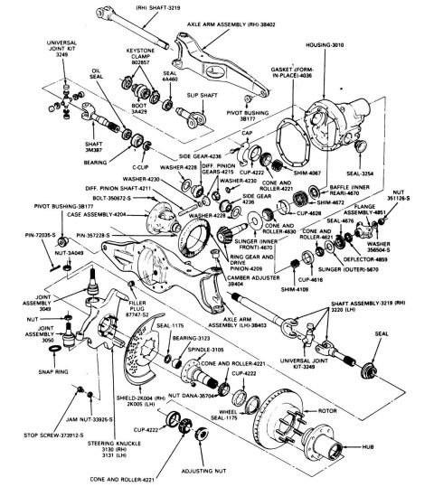
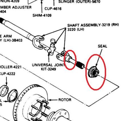


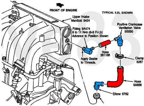
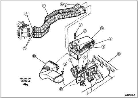
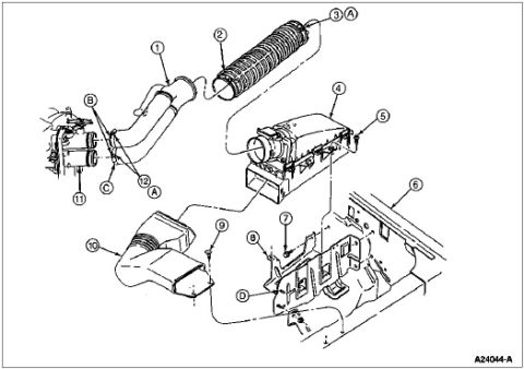
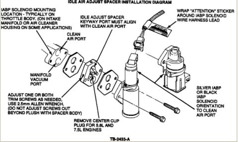
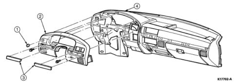
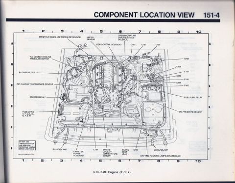









Exploded parts breakdown of a front axle assembly with part numbers for shaft, universal joint kit, seal, hub and rotor.
Part of 1987-1991 Ford Bronco Exploded Parts Diagrams
This document is a cropped exploded-parts diagram of a Ford front axle shaft and spindle/knuckle area, uploaded to illustrate the location of the spindle seal on a 1990 Ford Bronco. The line drawing shows the front axle shaft assembly (labeled SHAFT ASSEMBLY-3219 (RH) / 3220 (LH)) with its universal joint (UNIVERSAL JOINT KIT-3249), and two red circles have been added by the uploader to highlight the shaft's slip-yoke/seal area and the spindle seal itself, which is labeled simply 'SEAL'. Surrounding components are identified with Ford basic part numbers, including SHIM-4109, CUP-4616, SLINGER (OUTER)-5670, ROLLER-4221, CUP-4222, a steering arm labeled (LH)-3B403, and the brake ROTOR with its wheel studs. Some labels along the left and top edges are cut off by the crop (e.g., '-4209' and a partially visible 'MBER ADJUSTER ...404', likely a camber adjuster). A reader can learn the relative assembly order and identification numbers of the front axle shaft, spindle bearing components, seal, and rotor in this front hub/axle assembly.
Is this accurate? Sign in to help verify it.
Frequently asked questions
- What are the part numbers for the front axle shaft assemblies?
- The diagram labels the shaft assembly as 3219 (RH) and 3220 (LH).
- What part number is the universal joint kit for the axle shaft?
- The universal joint is labeled UNIVERSAL JOINT KIT-3249.
- Where is the spindle seal located in this assembly?
- The seal (labeled 'SEAL' and circled in red) sits between the axle shaft's stub/slip end and the spindle bearing components (ROLLER-4221 and CUP-4222), ahead of the rotor.
- What bearing components are shown near the spindle?
- The diagram shows ROLLER-4221 and CUP-4222, plus CUP-4616, SHIM-4109, and SLINGER (OUTER)-5670 elsewhere in the assembly.






No comments yet.