Home/
Registry/
Ford/
Bronco/
1987-1991/
1990 Ford Bronco/
Photo
supermotors.net/registry/media/485429
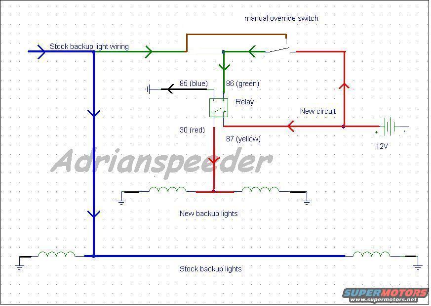
Ford Bronco Auxiliary Backup Lights Relay Wiring Diagram with Manual Override
Reference · 1987-1991 BroncoAll 175 wiring diagrams


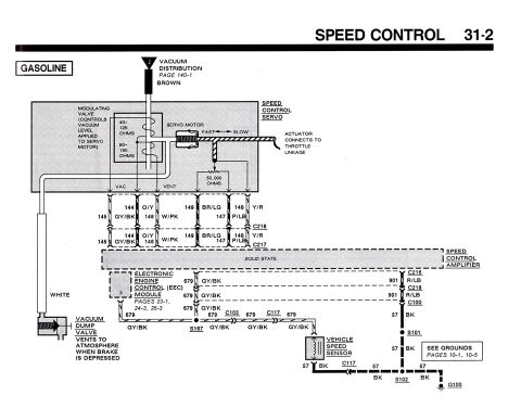
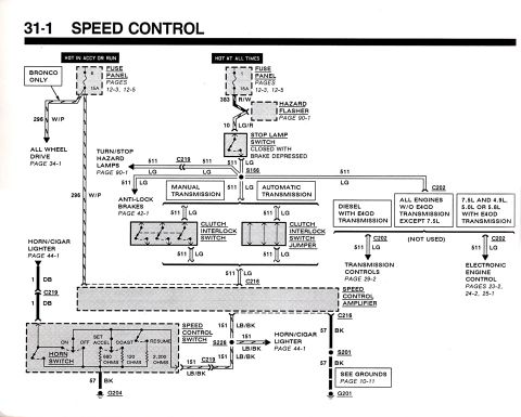
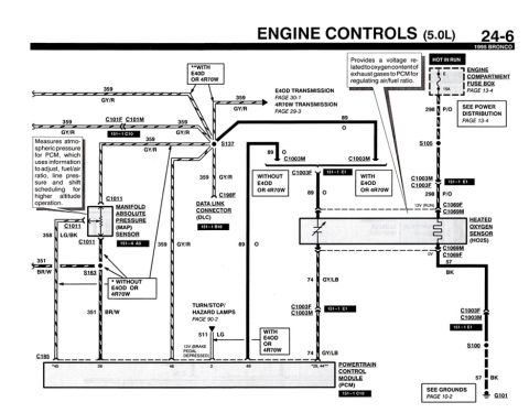
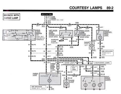










Wiring diagram adding new backup lights via a relay, showing color-coded 12V circuit, manual override switch, and stock wiring.
Part of 1987-1991 Ford Bronco Wiring Diagrams
This document is a hand-drawn/CAD-style wiring diagram (credited to 'Adrianspeeder', hosted on SuperMotors.net) showing how to add auxiliary backup lights to a vehicle using a relay with a manual override switch. The stock backup light wiring (shown in green) feeds relay terminal 86 (green wire), while relay terminal 85 (blue wire) goes to chassis ground. A new circuit (shown in red) runs from the 12V battery positive to relay terminal 87 (yellow wire), and relay terminal 30 (red wire) feeds the new backup lights, which are each grounded on their own side. A manual override switch (brown wire) allows the new circuit's 12V feed to be connected directly to the stock backup light wiring/relay trigger, so the new backup lights can be turned on manually rather than only when reverse is selected. The stock backup lights remain on their original circuit (shown in blue) with grounds at each lamp. The diagram identifies standard Bosch-style relay pin numbers (30, 85, 86, 87) with suggested wire colors, making it a useful reference for anyone wiring additional reverse/backup lights with both automatic (reverse-triggered) and manual operation.
Is this accurate? Sign in to help verify it.
Frequently asked questions
- Which relay terminal connects to the stock backup light wiring?
- Terminal 86 (green wire) is fed from the stock backup light wiring to trigger the relay.
- Which relay terminal goes to ground?
- Terminal 85 (blue wire) is connected to ground.
- How are the new backup lights powered?
- A new circuit (red) runs from the 12V battery to relay terminal 87 (yellow), and terminal 30 (red) feeds the new backup lights.
- What does the manual override switch do?
- It connects the 12V new circuit directly to the relay trigger/stock backup light wiring so the new backup lights can be switched on manually.
- What wire colors are suggested for the relay terminals?
- 85 = blue, 86 = green, 30 = red, 87 = yellow.






No comments yet.