Home/
Registry/
Ford/
Bronco/
1987-1991/
1990 Ford Bronco/
Photo
supermotors.net/registry/media/704691
Ford Bronco Front Axle Exploded Diagram - Dana TTB Parts & Part Numbers

Reference · 1987-1991 BroncoAll 64 exploded parts diagrams
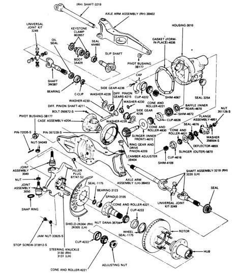
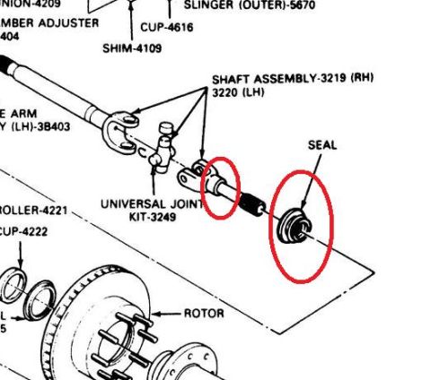


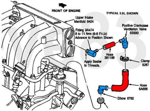
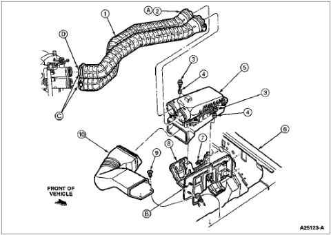
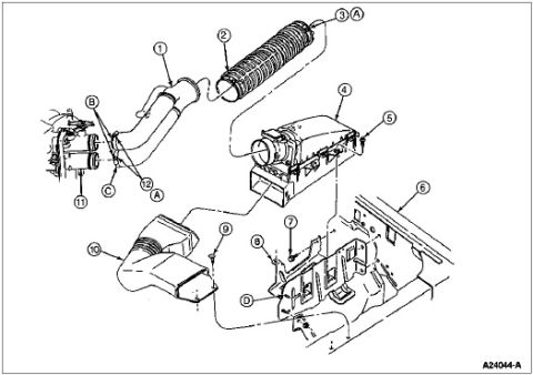
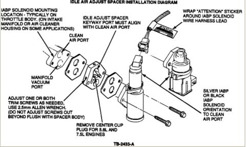
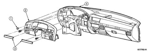
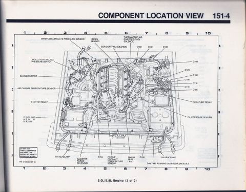










Comprehensive exploded parts breakdown of a Dana front axle with extensive part numbers for housing, gears, knuckles, hub and shafts.
Part of 1987-1991 Ford Bronco Exploded Parts Diagrams
This document is an exploded parts diagram of a Ford front driving axle assembly (Dana-style Twin Traction Beam front end), uploaded as a reference for a 1990 Ford Bronco. It shows every component of the front axle and hub assembly with Ford base part numbers, including the right-hand shaft (3219) and left-hand shaft (3220), axle arm assemblies (3B402 RH / 3B403 LH), the axle housing (3010), differential case assembly (4204), ring gear and drive pinion (4209), side gears (4236), differential pinion gears (4215) and shaft (4211), plus associated washers, shims, bearings (cone-and-roller sets 4221, 4621, 4630 with cups 4222, 4616, 4628), seals, slingers, baffles, and the pinion flange assembly (4851). The outer end components are also detailed: universal joint kit (3249), slip shaft with boot (3A429) and keystone clamp (802857), camber adjuster (3B404), ball joint assemblies (3049 upper, 3050 lower), steering knuckle (3130 RH / 3131 LH), spindle (3105), spindle bearing (3123), seals (1175), brake shield (2K004 RH / 2K005 LH), rotor, hub, and wheel bearing adjusting nut (Dana 35704). Readers can use it to identify part numbers and assembly order when rebuilding the front axle, knuckles, spindles, or wheel bearings.
Is this accurate? Sign in to help verify it.
Frequently asked questions
- What is the part number for the front spindle?
- The spindle is labeled 3105, with spindle bearing 3123 and seal 1175 shown adjacent to it.
- What are the part numbers for the axle shafts?
- The shaft assembly is 3219 for the right-hand side and 3220 for the left-hand side; a separate shaft 3M387 and a slip shaft are also shown.
- What part numbers are the steering knuckles and brake shields?
- Steering knuckle 3130 (RH) and 3131 (LH); brake shield 2K004 (RH) and 2K005 (LH).
- What ball joint part numbers are shown?
- Joint assembly 3049 (upper) and joint assembly 3050 (lower), along with a nut and snap ring.
- What wheel bearing components are shown at the hub?
- Cone and roller 4221 with cup 4222 (inner and outer), wheel seal 1175, adjusting nut, nut Dana-35704, rotor, and hub.






No comments yet.