Ford FS-6 A/C Compressor Clutch & Head Exploded Diagram - Specs & Part Numbers

Reference · 1987-1991 BroncoAll 64 exploded parts diagrams

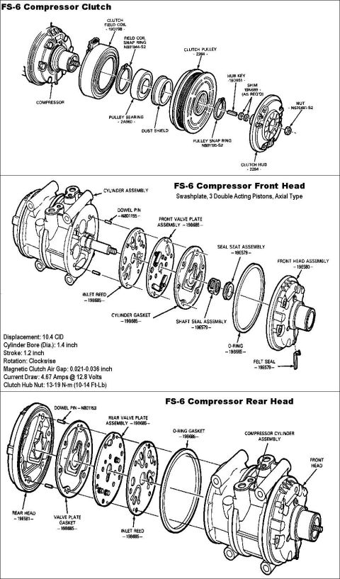









Exploded parts diagram of the FS-6 air-conditioning compressor with clutch, front head and rear head components and specs.
Part of 1987-1991 Ford Bronco Exploded Parts Diagrams
This document is a three-part exploded parts diagram for the Ford FS-6 air conditioning compressor, a swashplate-type axial compressor with 3 double-acting pistons. The first diagram shows the compressor clutch assembly, labeling components in disassembly order: clutch field coil (19D798), field coil snap ring (N801944-S2), pulley bearing (2A980), dust shield, clutch pulley (2284), pulley snap ring (N801195-S2), hub key (19D651), shims (19N689, as required), clutch hub (2284), and retaining nut (N620481-S2). The second diagram covers the front head, showing the cylinder assembly, dowel pin (N801155), inlet reed, front valve plate assembly and cylinder gasket (19B685), shaft seal and seal seat assemblies (19E579), O-ring, felt seal, and front head assembly (19E580). The third diagram shows the rear head assembly: dowel pin (N801153), valve plate gasket, rear valve plate assembly, inlet reed, O-ring gasket (all 19B685), and rear head (19E581). Key specifications are listed: 10.4 CID displacement, 1.4-inch bore, 1.2-inch stroke, clockwise rotation, magnetic clutch air gap of 0.021-0.036 inch, current draw of 4.67 amps at 12.8 volts, and clutch hub nut torque of 13-19 N-m (10-14 ft-lb). Useful for rebuilding or servicing the FS-6 compressor and clutch.
Is this accurate? Sign in to help verify it.
Frequently asked questions
- What is the magnetic clutch air gap spec for the Ford FS-6 compressor?
- The magnetic clutch air gap is 0.021-0.036 inch.
- What is the clutch hub nut torque on the FS-6 compressor?
- 13-19 N-m (10-14 Ft-Lb).
- What type of compressor is the FS-6?
- It is a swashplate, axial-type compressor with 3 double-acting pistons, 10.4 CID displacement, 1.4-inch cylinder bore, 1.2-inch stroke, and clockwise rotation.
- What is the current draw of the FS-6 clutch coil?
- 4.67 amps at 12.8 volts.
- What parts make up the FS-6 clutch assembly?
- The clutch field coil (19D798), field coil snap ring (N801944-S2), pulley bearing (2A980), dust shield, clutch pulley (2284), pulley snap ring (N801195-S2), hub key (19D651), shims (19N689, as required), clutch hub (2284), and nut (N620481-S2).






No comments yet.