1980-96 Ford Bronco Body Mount Locations Diagram - Frame Mount Positions 1-4

Reference · 1987-1991 BroncoAll 64 exploded parts diagrams
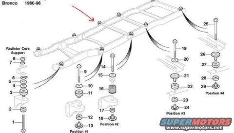
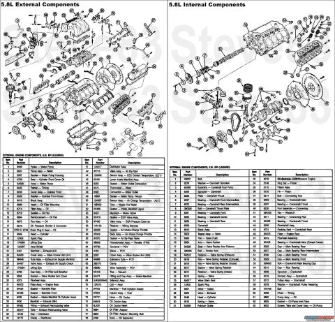
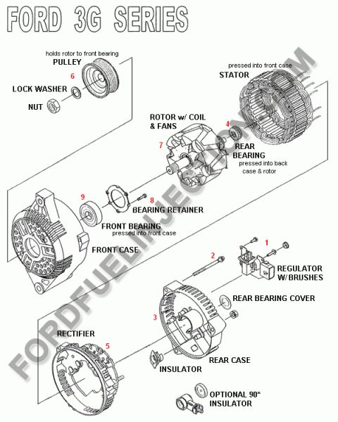
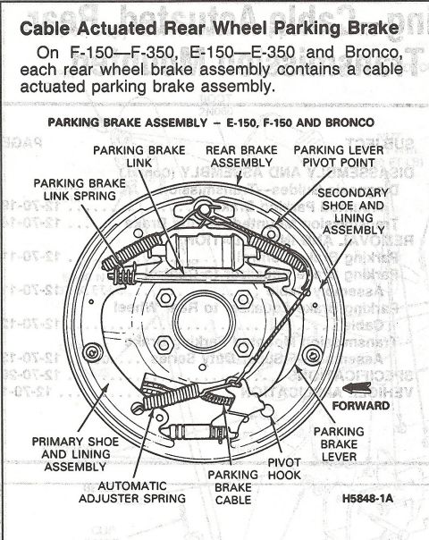

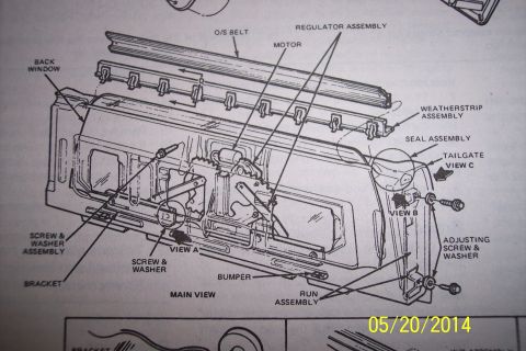









Exploded parts diagram of 1980-96 Bronco body mounts showing numbered bolts, washers and bushings by position.
Part of 1987-1991 Ford Bronco Exploded Parts Diagrams
This document is an exploded parts diagram showing the body mount locations and hardware for the 1980-1996 Ford Bronco. It depicts the full frame (chassis) in a perspective view with leader lines pointing from each mounting point on the frame rails to exploded stacks of mounting hardware. The diagram identifies four labeled mounting positions along the frame, Position #1, Position #2, Position #3, and Position #4, plus a separate hardware stack for the Radiator Core Support at the front. Numbered callouts 1 through 29 identify individual components such as bolts, washers, rubber insulators/bushings, spacers, brackets, and nuts that make up each body mount assembly. A reader can learn how many body mount positions the Bronco frame uses, where each mount is located along the frame, and the order in which the mount hardware components stack together at each position (upper insulator, lower insulator, retainers, and fasteners). The diagram does not include a parts legend with names or part numbers for the numbered callouts, nor torque specifications; it serves as a visual location and assembly-order reference. The image carries a SuperMotors.net watermark.
Is this accurate? Sign in to help verify it.
Frequently asked questions
- What years of Ford Bronco does this body mount diagram cover?
- The diagram is labeled 'Bronco 1980-96', so it covers 1980 through 1996 Ford Broncos.
- How many body mount positions are shown on the Bronco frame?
- The diagram labels four body mount positions along the frame, Position #1, Position #2, Position #3, and Position #4, plus a separate mount stack for the Radiator Core Support at the front of the frame.
- Does the diagram show the radiator core support mount?
- Yes, a hardware stack labeled 'Radiator Core Support' (callouts 1-8) is shown at the front of the frame.
- How many individual parts are called out in the diagram?
- The diagram uses numbered callouts 1 through 29 to identify the bolts, washers, insulators/bushings, brackets, and other hardware at each mount position.
- Does this diagram list part numbers or torque specs for the body mounts?
- No. It only shows numbered callouts and mount positions; no part numbers, part names, or torque values are printed on the diagram.






No comments yet.