Ford FX-15 A/C Compressor Clutch Exploded Diagram - Air Gap & Manifold O-Rings
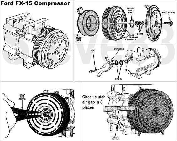
Exploded parts and service diagram of the Ford FX-15 AC compressor showing clutch, pulley, manifold and clutch air-gap check.
Part of 1987-1991 Ford Bronco Exploded Parts Diagrams
This document is a multi-panel illustrated reference for the Ford FX-15 air conditioning compressor and its clutch assembly. The top-left panel shows the fully assembled compressor. The top-right panel is an exploded view of the clutch components, labeling the hub, 6 mm bolt, pulley snap ring, field coil, pulley and bearing assembly, and shims, showing their order of assembly on the compressor nose. A middle-right panel illustrates the refrigerant manifold attachment, identifying the bolt, manifold, and O-rings that seal the manifold to the compressor body. The bottom-left panel demonstrates using snap ring pliers to remove the pulley snap ring from the clutch. The bottom-right panel shows how to check clutch air gap with a feeler gauge, with the instruction to 'check clutch air gap in 3 places' around the clutch face. A reader can learn the component makeup and disassembly/reassembly sequence of the FX-15 compressor clutch, the location of manifold O-ring seals, and the proper method for verifying clutch air gap during service. No torque values, part numbers, or specific gap specifications are printed on the document.
Is this accurate? Sign in to help verify it.
Frequently asked questions
- What components make up the Ford FX-15 compressor clutch assembly?
- The exploded view shows the hub, a 6 mm bolt, pulley snap ring, pulley and bearing assembly, shims, and the field coil.
- How do you check the clutch air gap on an FX-15 compressor?
- Use a feeler gauge and check the clutch air gap in 3 places around the clutch face, as shown in the bottom-right illustration.
- How is the pulley removed from the FX-15 compressor?
- The diagram shows using snap ring pliers to remove the pulley snap ring that retains the pulley and bearing assembly.
- What seals the refrigerant manifold on the FX-15 compressor?
- The manifold is attached with a bolt and sealed to the compressor with O-rings, as shown in the manifold illustration.
- What adjusts the clutch air gap on the FX-15?
- Shims are shown between the pulley/bearing assembly and hub in the exploded view; these set the clutch spacing that is verified with a feeler gauge.
Comments
More from this build














No comments yet.