Home/
Registry/
Ford/
Bronco/
1987-1991/
1989 Ford Bronco/
Photo
supermotors.net/registry/media/854906
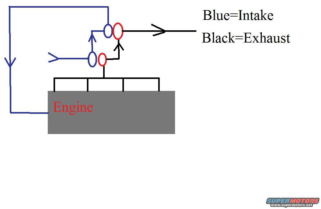
Turbocharger Airflow Schematic - Intake & Exhaust Flow Diagram (Ford Bronco)
Reference · 1987-1991 BroncoAll 111 schematics















Schematic of engine intake and exhaust flow with color-coded intake and exhaust routing.
Part of 1987-1991 Ford Bronco Schematics
This document is a simple hand-drawn schematic (filename turbo2.jpg) illustrating airflow through a turbocharger setup on an engine, uploaded to a 1989 Ford Bronco gallery. The only text present is a two-line color legend, "Blue=Intake" and "Black=Exhaust", plus the label "Engine" on a gray block. The drawing shows exhaust gases (black lines) collected from four points on the engine, merging into one pipe that feeds what appears to be a two-stage or twin turbo arrangement (drawn as paired red and blue ovals), then exiting to the right as the exhaust outlet. Intake air (blue lines) enters from the left, passes through the compressor side of the turbo(s), and is routed around the left side of the diagram back down into the engine. Arrows indicate flow direction for both intake and exhaust paths. The document contains no part numbers, fuse data, wire colors, torque values, model years, or vehicle-specific information, it is purely a conceptual flow diagram a reader can use to understand basic turbocharger plumbing (exhaust drives the turbine, compressed intake air feeds the engine).
Is this accurate? Sign in to help verify it.
Frequently asked questions
- What do the colors in this turbo diagram mean?
- The legend states Blue=Intake and Black=Exhaust.
- How does exhaust flow in this schematic?
- Four black exhaust lines from the engine merge into a single pipe feeding the turbo, and exhaust then exits to the right, shown with a black arrow.
- Where does intake air go in this diagram?
- Blue intake lines enter from the left, pass through the turbo (blue oval), and route around the left side down into the engine, with arrows showing flow direction.
- Does this diagram include part numbers or specifications?
- No. It is a conceptual flow schematic with only a color legend and an 'Engine' label, no part numbers, sizes, or specs are shown.






No comments yet.