Home/
Registry/
Ford/
Bronco/
1987-1991/
1989 Ford Bronco/
Photo
supermotors.net/registry/media/854907
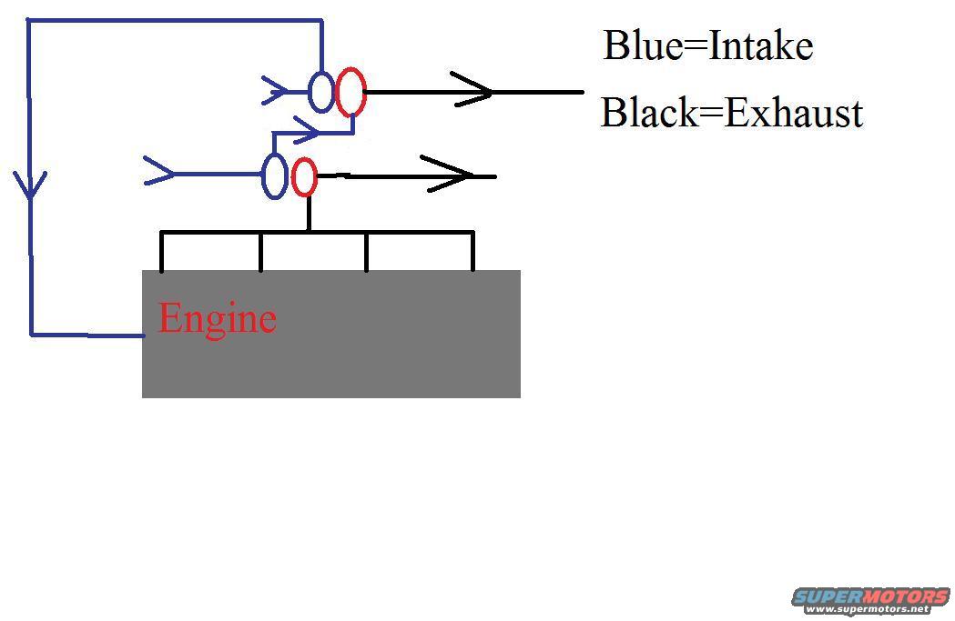
Twin Turbo Intake & Exhaust Flow Schematic - 1989 Ford Bronco Turbo Concept
Reference · 1987-1991 BroncoAll 110 schematics















Schematic of engine intake and exhaust flow with color-coded intake and exhaust routing.
Part of 1987-1991 Ford Bronco Schematics
This is a simple hand-drawn schematic (created in a basic paint program) illustrating a twin-turbocharger airflow routing concept for an engine. A gray rectangle labeled "Engine" in red text sits at the bottom, with four exhaust runners drawn in black feeding upward to two turbochargers, each represented by a pair of blue and red ovals (compressor and turbine sides). Blue lines with arrowheads show the intake air path: air enters each turbo's compressor side, and the pressurized intake charge routes leftward and down along the left side of the drawing back into the engine. Black lines with arrows show the exhaust flow exiting the turbine side of each turbo to the right. A legend at the top right states "Blue=Intake" and "Black=Exhaust." The diagram contains no part numbers, dimensions, torque specs, year/model applicability, or wiring information, it is purely a conceptual flow diagram showing how intake and exhaust plumbing would be arranged in a sequential or parallel twin-turbo setup. It appears to be page three (turbo3.jpg) of a multi-page set of similar turbo concept sketches uploaded to a 1989 Ford Bronco gallery.
Is this accurate? Sign in to help verify it.
Frequently asked questions
- What do the colors mean in this turbo diagram?
- Per the legend, blue lines represent the intake air path and black lines represent the exhaust flow.
- How many turbochargers are shown in the schematic?
- Two turbochargers are depicted, each drawn as a pair of blue and red ovals connected above the engine.
- How does the exhaust route in this diagram?
- Black exhaust lines run from the engine up to the turbos, and exhaust exits each turbo to the right, indicated by black arrows.
- Where does the intake air go after the turbos?
- Blue intake lines route from the turbos leftward and down the left side of the drawing back into the engine.






No comments yet.