1995 Ford Bronco TFI Ignition Control Module Connector C1021 Pinout Diagram

Reference · 1987-1991 BroncoAll 175 wiring diagrams
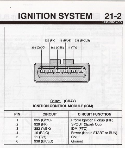














Ignition system diagram (21-2, 1995 Bronco) showing ICM connector C1021 pinout with circuit colors and a pin function table.
Part of 1987-1991 Ford Bronco Wiring Diagrams
This document is a scanned page (labeled "Ignition System 21-2") from a 1995 Ford Bronco wiring reference. It shows the connector face view and pinout for connector C1021 (gray), which plugs into the Ignition Control Module (ICM), commonly known as the TFI module. The diagram illustrates a 6-pin connector with each cavity labeled 1 through 6 and its corresponding circuit number and wire color called out: 395 (Gray/Orange), 929 (Pink), 382 (Yellow/Black), 16 (Red/Light Green), 11 (Tan/Yellow), and 938 (Black/Light Green). A table below the diagram defines each pin's function: Pin 1 is the Profile Ignition Pickup (PIP) signal, Pin 2 is SPOUT (Spark Out), Pin 3 is IDM (FTO), Pin 4 is Power (hot in START or RUN), Pin 5 is Coil, and Pin 6 is Ground. A reader can use this page to identify wire colors and circuit numbers at the ICM/TFI connector for diagnosing no-spark conditions, testing PIP and SPOUT signals, verifying ignition power feed, or repairing damaged wiring on a 1995 Bronco ignition system.
This document covers 1995, which may differ from this 1990 Ford Bronco.
Is this accurate? Sign in to help verify it.
Frequently asked questions
- What is the pinout of the 1995 Ford Bronco ignition control module (TFI) connector C1021?
- Pin 1: circuit 395 (GY/O) Profile Ignition Pickup (PIP); Pin 2: 929 (PK) SPOUT (Spark Out); Pin 3: 382 (Y/BK) IDM (FTO); Pin 4: 16 (R/LG) Power (Hot in START or RUN); Pin 5: 11 (T/Y) Coil; Pin 6: 938 (BK/LG) Ground.
- What wire color is the SPOUT signal on a 1995 Bronco ICM connector?
- SPOUT (Spark Out) is circuit 929, a Pink (PK) wire on pin 2 of connector C1021.
- Which pin provides power to the 1995 Bronco ignition control module?
- Pin 4, circuit 16 (Red/Light Green, R/LG), which is hot in START or RUN.
- What color is the ICM connector C1021 on the 1995 Bronco?
- The document identifies connector C1021 as GRAY.
- Which pin on the ICM connector goes to the ignition coil?
- Pin 5, circuit 11 (Tan/Yellow, T/Y), is the Coil circuit.






No comments yet.