Home/
Registry/
Ford/
Bronco/
1992-1996/
“pukin' dogII”/
Photo
supermotors.net/registry/media/877795
1996 Ford Bronco Manual Shift Transfer Case Diagram - Front & Rear Views (C7860-E)

Reference · 1992-1996 BroncoAll 169 exploded parts diagrams
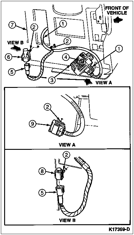






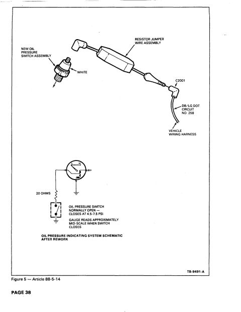
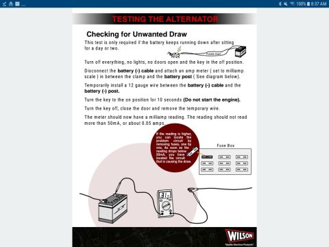
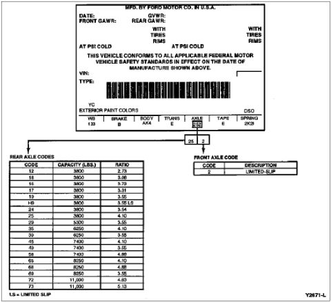

Front and rear view component drawing of a transfer case with numbered callouts identifying parts.
Part of 1992-1996 Ford Bronco Exploded Parts Diagrams
This document is a single-page line-art illustration (Ford figure reference C7860-E) showing two views of a transfer case assembly: a FRONT VIEW and a REAR VIEW. The front view carries numbered callouts 1 through 6 pointing to features on the front of the case, including the front output/bearing retainer area (callout 6), fittings and fasteners along the top of the case (callouts 1-3), a mid-case boss (callout 5), and the rear output area (callout 4). The rear view repeats callout 4 at the rear output bearing retainer and shows callout 7 at two lower case bolt/plug locations. No legend, parts table, or text key accompanies the illustration on this page, so the identity of each numbered item cannot be determined from this scan alone; it was likely accompanied by a separate legend page in the original service manual. The file was uploaded as part of a 1996 Ford Bronco documentation album and is labeled as pertaining to the manual-shift transfer case. Readers can use the drawing to locate external components, plugs, sensors, and fastener positions on the front and rear faces of the transfer case housing.
Is this accurate? Sign in to help verify it.
Frequently asked questions
- What does this diagram show?
- It shows two illustrated views of a transfer case housing, a FRONT VIEW with callouts 1 through 6 and a REAR VIEW with callouts 4 and 7, identified by Ford figure number C7860-E.
- Does the diagram include a legend explaining the numbered callouts?
- No. The page contains only the illustration with callout numbers 1-7; no legend or descriptions of the numbered items are visible on this page.
- How many callouts are on each view?
- The front view has callouts 1, 2, 3, 4, 5, and 6. The rear view shows callout 4 (at the rear output area) and callout 7 at two lower locations.
- Is there a figure or reference number on the drawing?
- Yes, the figure reference C7860-E appears at the bottom right of the illustration.






No comments yet.