Home/
Registry/
Ford/
Bronco/
1992-1996/
“pukin' dogII”/
Photo
supermotors.net/registry/media/877797
1996 Ford Bronco Front Driveshaft Diagram - Double Cardan Joint & Slip-Yoke

Reference · 1992-1996 BroncoAll 169 exploded parts diagrams
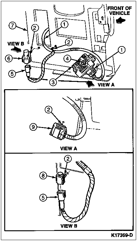
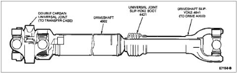
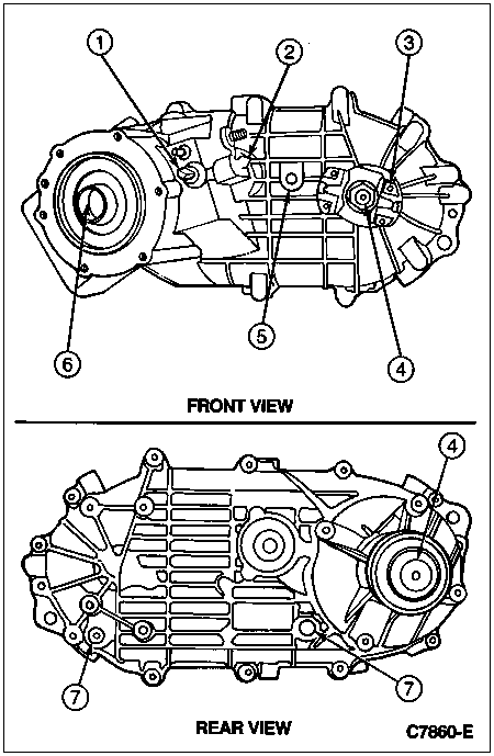
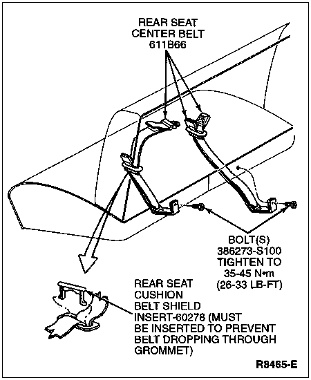
Labeled driveshaft component diagram identifying the double cardan U-joint, slip-yoke boot and end yokes.
Part of 1992-1996 Ford Bronco Exploded Parts Diagrams
This document is a labeled line drawing of a driveshaft assembly, uploaded to a 1996 Ford Bronco gallery. The diagram shows a complete driveshaft in side view with four callouts identifying its major components: the double cardan universal joint at one end (which connects to the transfer case), the main driveshaft tube (base part number 4602), the universal joint slip-yoke boot (base part number 4421), and the driveshaft slip-yoke (base part number 4841) at the opposite end, which connects to the drive axle. The illustration reference number E7154-B appears at the lower right of the frame. A reader can learn the orientation of the driveshaft (double cardan joint toward the transfer case, slip-yoke toward the axle), the Ford base part group numbers for the shaft, boot, and slip-yoke, and the general construction of the assembly including the accordion-style boot covering the slip-yoke splines. The document itself contains no year, model, or engine applicability statements, so its exact application must be inferred from context; it is filed as part of a set of 1996 Bronco reference scans.
Is this accurate? Sign in to help verify it.
Frequently asked questions
- What are the main parts of the driveshaft shown in this diagram?
- The diagram labels four items: the double cardan universal joint (to transfer case), the driveshaft (4602), the universal joint slip-yoke boot (4421), and the driveshaft slip-yoke (4841, to drive axle).
- Which end of the driveshaft connects to the transfer case?
- The end with the double cardan universal joint connects to the transfer case, per the callout in the diagram.
- What is the Ford base part number for the driveshaft slip-yoke?
- The slip-yoke is labeled 4841, and it connects to the drive axle.
- What part number is given for the slip-yoke boot?
- The universal joint slip-yoke boot is labeled 4421.
No comments yet.