Home/
Registry/
Ford/
Bronco/
1992-1996/
“pukin' dogII”/
Photo
supermotors.net/registry/media/877796
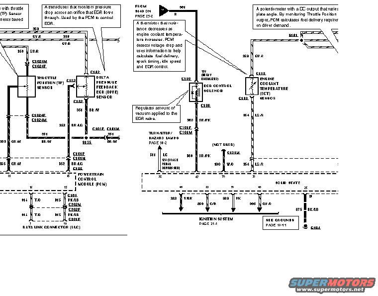
1996 Ford Bronco 5.8 DPFE/EGR & PCM Wiring Diagram - TP, ECT Sensor Circuits
Reference · 1992-1996 BroncoAll 411 wiring diagrams
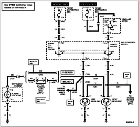
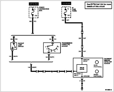
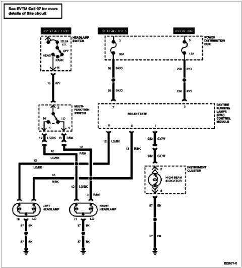
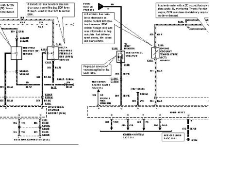













Electrical wiring diagram showing PCM, EGR feedback, throttle position and coolant temperature sensors with color codes.
Part of 1992-1996 Ford Bronco Wiring Diagrams
This scan is a portion of a factory-style engine control wiring diagram, filed by the uploader as covering the DPFE/EGR wiring on a 1996 Ford Bronco with a 5.8L engine. It shows the Powertrain Control Module (PCM) and its connections to the Throttle Position (TP) Sensor, the Delta Pressure Feedback EGR (DPFE) Sensor, the EGR Control Solenoid, and the Engine Coolant Temperature (ECT) Sensor, plus the Data Link Connector (DLC). Circuit numbers and wire colors are labeled throughout, including 359 GY/R (sensor reference), 351 BR/W, 352 BR/LG and Y/BK, 354 LG/R, 355 GY/W, 360 BR/PK, 511 LG, 190 W/O, 914/915 T/O and PK/LB (DLC), 259 O/R, 229 PK, and 875 BK/LB to ground G104. Connectors identified include C1024M/F, C182, C101F/M, C105, C113, C130, C185, C201F/C202N/C202F, with splices S135 and S161. Explanatory callouts describe how the DPFE transducer, TP potentiometer, and ECT thermistor operate and how the EGR solenoid regulates vacuum to the EGR valve. Cross-references point to the Ignition System (page 21-1), Turn/Stop/Hazard Lamps (page 90-2), Grounds (page 14-11), and splice S140 on page 25-2.
Is this accurate? Sign in to help verify it.
Frequently asked questions
- What wire color is the sensor reference circuit 359 on this diagram?
- Circuit 359 is shown as GY/R (gray/red), feeding the TP sensor, DPFE sensor, and ECT sensor; a GY/O branch also appears near the PCM.
- Which connector serves the DPFE sensor?
- The Delta Pressure Feedback EGR (DPFE) sensor connects through connector C182, with circuit 351 BR/W and 352 BR/LG wiring shown.
- What does the DPFE sensor do according to the diagram's callout?
- It is a transducer that monitors pressure drop across an orifice that EGR flows through, and is used by the PCM to control EGR.
- How does the EGR control solenoid work per this diagram?
- The EGR control solenoid (connector C130) regulates the amount of vacuum applied to the EGR valve; it is fed +12V with the relay energized and its control wire is circuit 360 BR/PK to the PCM.
- Where does the ground circuit for this system go?
- Circuit 875 BK/LB runs to ground G104, with a note to see Grounds on page 14-11.






No comments yet.