Home/
Registry/
Ford/
Bronco/
1992-1996/
“pukin' dogII”/
Photo
supermotors.net/registry/media/877836
1996 Ford Bronco Keyless Entry Antenna Plug (C3) Diagram - Signal & Ground

Reference · 1992-1996 BroncoAll 95 schematics

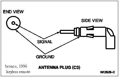









Schematic of the antenna plug (C3) connector showing end and side views with signal and ground terminals labeled.
Part of 1992-1996 Ford Bronco Schematics
This document is a simple line-art schematic showing the antenna plug (connector C3) for the keyless entry remote system, uploaded as applying to a 1996 Ford Bronco. The diagram presents two views of the coaxial-style antenna connector: an END VIEW, drawn as a circle with a center pin, and a SIDE VIEW, drawn as an elongated right-angle plug with a protruding center conductor. Callout arrows identify the two electrical contact points: SIGNAL, indicated at the small center pin in the end view and at the tip of the center conductor in the side view, and GROUND, indicated at the outer shell/body of the connector in both views. The drawing is labeled "ANTENNA PLUG (C3)" and carries the Ford illustration reference number N12626-C. A handwritten-style notation "bronco, 1996 keyless remote" appears in the lower left corner, identifying the application. A reader can learn how to identify the signal versus ground contacts on the keyless entry antenna connector when testing or repairing the remote keyless entry antenna circuit.
Is this accurate? Sign in to help verify it.
Frequently asked questions
- What connector does this diagram show?
- It shows the ANTENNA PLUG, identified as connector C3, for the 1996 Bronco keyless remote system.
- Which contact is the signal on the keyless entry antenna plug?
- The SIGNAL is the center pin/conductor of the plug, shown at the center of the end view and at the tip of the connector in the side view.
- Where is the ground on the antenna plug C3?
- The GROUND is the outer shell/body of the connector, indicated by arrows in both the end view and side view.
- Is there a reference number for this illustration?
- Yes, the diagram carries the reference number N12626-C.






No comments yet.