Home/
Registry/
Ford/
Bronco/
1992-1996/
“pukin' dogII”/
Photo
supermotors.net/registry/media/877837
1996 Ford Bronco 4WABS Wiring Diagram - ABS Module Connector Pinout & Circuits

Reference · 1992-1996 BroncoAll 411 wiring diagrams
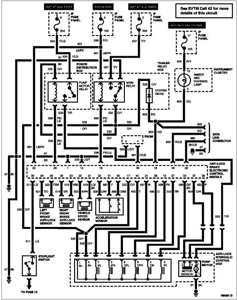
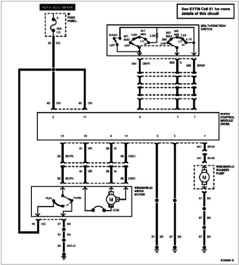
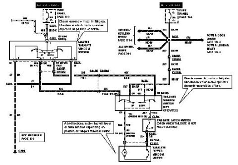
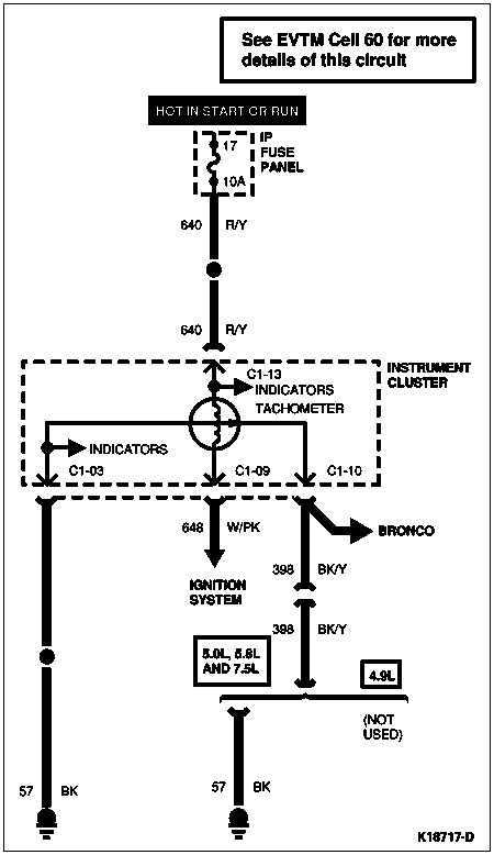
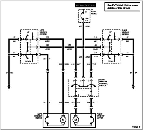













Wiring diagram of the anti-lock brake control module showing fuse panels, relays, sensors and color-coded circuit wiring.
Part of 1992-1996 Ford Bronco Wiring Diagrams
This document is a wiring diagram for the 4-wheel anti-lock brake system (4WABS) on a mid-1990s Ford truck, uploaded to a 1996 Ford Bronco gallery. It shows power feeds from the IP fuse panel: fuse 8 (30A, hot at all times), fuse 5 (15A, hot in run), fuse 2 (30A, hot at all times), and fuse 17 (10A, hot in start or run). Power routes through the pump motor relay and main relay in the power distribution box, and a system diode in the trailer relay box, to the anti-lock brake electronic control module. The diagram identifies module connector pin numbers (1-40 range shown) and circuit numbers with wire colors, such as 534 Y/LG, 601 LB/PK, 532 O/Y, 603 DG, 530 LG/Y, and 511 LG. Connected components include the amber ABS warning lamp in the instrument cluster, the data link connector, PSOM connector, left and right front wheel anti-lock sensors, vehicle speed sensor, acceleration sensor, stoplight switch (feeding fuse 13), and the anti-lock hydraulic control unit with pump motor and motor sensor (pins labeled B+, IFL, IFR, OFL, OFR, OR, IR). A note references EVTM Cell 42 for more circuit details. Diagram reference number H8686-D appears at bottom right.
Is this accurate? Sign in to help verify it.
Frequently asked questions
- Which fuses power the 4-wheel ABS system?
- Per the diagram: IP fuse panel fuse 8 (30A, hot at all times), fuse 5 (15A, hot in run), fuse 2 (30A, hot at all times), and fuse 17 (10A, hot in start or run).
- What wire circuit feeds the ABS warning lamp?
- The amber ABS warning lamp in the instrument cluster is fed by circuit 640 R/Y from fuse 17 (10A) at pin 13, with output on circuit 603 DG at pin 3 going to the ABS module and data link connector.
- Where are the pump motor relay and main relay located?
- Both the pump motor relay and the main relay are shown inside the power distribution box; the system diode is in the trailer relay box.
- What are the wheel speed sensor wire colors?
- Left front brake anti-lock sensor uses circuits 521 T/O and 522 T/BK; the right front sensor uses 514 Y/R and 516 Y/BK. The vehicle speed sensor uses 523 R/PK and 519 LG/BK.
- What are the hydraulic control unit connector pin assignments?
- Pins are labeled 1 B+, 4 B+, 7 IFL, 5 IFR, 6 OFL, 8 OFR, 2 OR, and 3 IR, plus a pump motor/motor sensor connector with pins 1-4 and a 57 BK ground.






No comments yet.