1996 Ford Probe 2.5L V6 Cooling Fan Wiring Diagram - Relays, PCM & Fuses
Reference · 1993-1997 ProbeAll 65 wiring diagrams
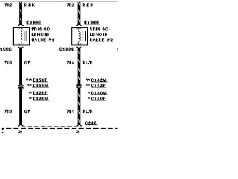
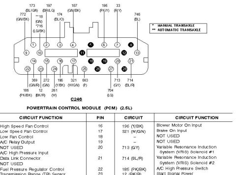
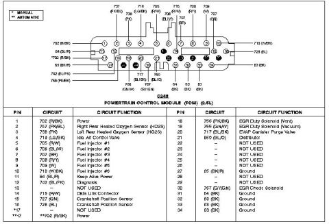
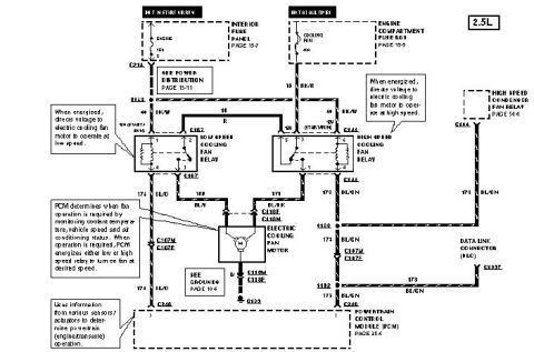
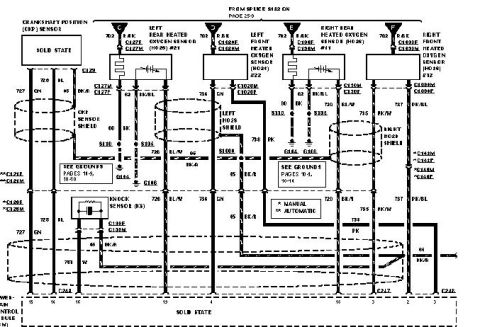
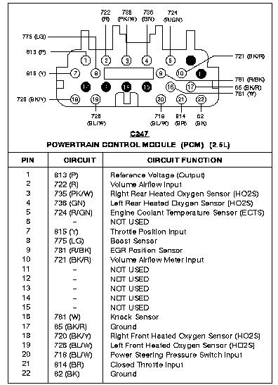
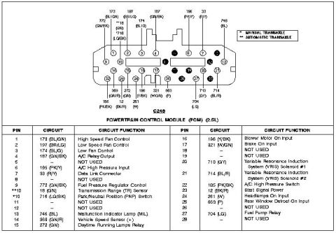









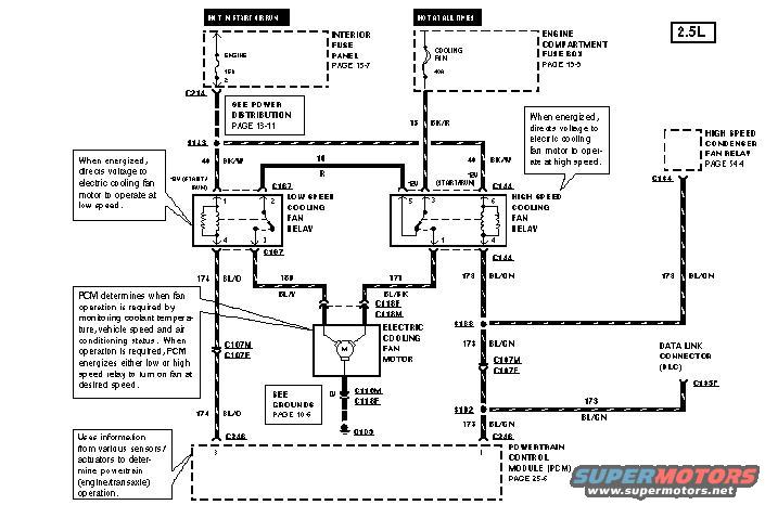
Wiring diagram showing low- and high-speed cooling fan relays, cooling fan motor and PCM control circuits.
Part of 1993-1997 Ford Probe Wiring Diagrams
This document is a factory-style wiring diagram for the electric engine cooling fan circuit on a 2.5L (V6) Ford Probe. It shows power feeds from two sources: a 15A ENGINE fuse in the interior fuse panel (hot in start or run) and a 40A COOLING FAN fuse in the engine compartment fuse box (hot at all times). Power flows through splice S113 and circuit 44 (BK/W wire) to the low speed cooling fan relay (connector C167) and high speed cooling fan relay (connector C144). Each relay, when energized, directs voltage to the electric cooling fan motor to run at low or high speed, respectively; the diagram also references the high speed condenser fan relay (page 34-4). The fan motor connects through connectors C118M/C118F and grounds at G103. Control comes from the Powertrain Control Module (PCM, connector C246), which monitors coolant temperature, vehicle speed and A/C status, then energizes the low speed relay via circuit 174 (BL/O) or the high speed relay via circuit 173 (BL/GN), which also ties to the Data Link Connector (DLC, C193F). Wire colors, circuit numbers, splices (S113, S135, S192) and inline connectors (C107M/F, C187M/F, C214) are labeled throughout.
Is this accurate? Sign in to help verify it.
Frequently asked questions
- What fuses power the cooling fan circuit on the 2.5L Probe?
- A 15A ENGINE fuse in the interior fuse panel (hot in start or run) and a 40A COOLING FAN fuse in the engine compartment fuse box (hot at all times).
- How does the PCM control the cooling fan?
- The PCM determines when fan operation is required by monitoring coolant temperature, vehicle speed and air conditioning status, then energizes either the low speed or high speed relay to turn on the fan at the desired speed.
- What are the relay connectors for the cooling fan relays?
- The low speed cooling fan relay uses connector C167 and the high speed cooling fan relay uses connector C144.
- What wire colors are used in the fan control circuits?
- Circuit 44 is BK/W, circuit 15 is BK/R, circuit 16 is R, circuit 174 is BL/O, circuit 171 is BL/Y and BL/BK, and circuit 173 is BL/GN.
- Where does the cooling fan motor ground?
- The fan motor grounds through a B (black) wire to ground point G103, referenced to 'SEE GROUNDS PAGE 10-6'.






No comments yet.