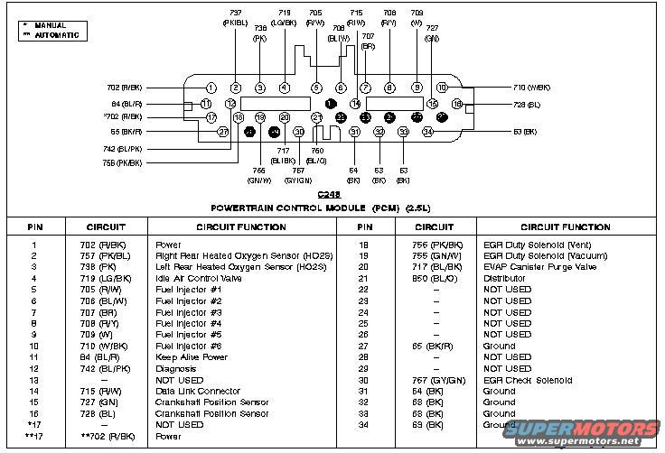
1996 Ford Probe 2.5L PCM Connector C248 Pinout - Wire Colors & Functions
Reference · 1993-1997 ProbeAll 65 wiring diagrams
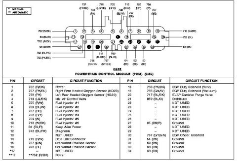
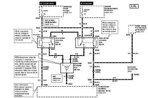
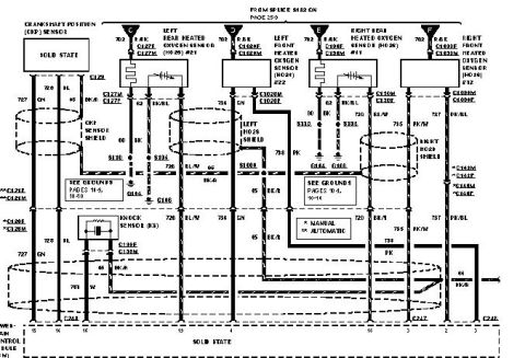
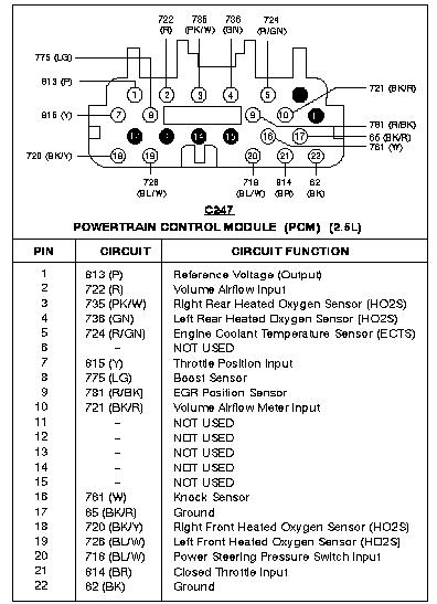
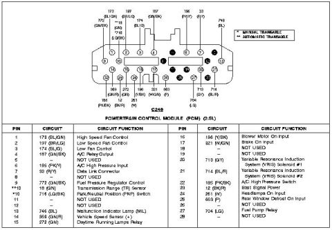









Powertrain control module connector C248 pinout with color-coded pins and circuit-function reference table.
Part of 1993-1997 Ford Probe Wiring Diagrams
This document is a connector pinout reference for connector C248 of the Powertrain Control Module (PCM) on a 2.5L engine (per the album context, a mid-1990s Ford Probe with the 2.5L V6). It shows a face view of the 34-pin PCM connector with wire circuit numbers and color codes labeled around the connector body, followed by a two-column pinout table listing each of the 34 pins, its circuit number and wire color, and its circuit function. Covered circuits include PCM power (pin 1, 702 R/BK), heated oxygen sensors (pins 2-3), idle air control valve (pin 4), fuel injectors #1-#6 (pins 5-10), keep alive power (pin 11), diagnosis (pin 12), data link connector (pin 14), crankshaft position sensor (pins 15-16), EGR duty solenoids for vent and vacuum (pins 18-19), EVAP canister purge valve (pin 20), distributor (pin 21), EGR check solenoid (pin 31), and multiple grounds (pins 27, 32, 33, 34). A legend distinguishes manual (*) from automatic (**) transmission variants, notably pin 17, which is NOT USED on manual but is a 702 (R/BK) power feed on automatic. Several pins (13, 22-26, 28) are marked NOT USED.
Is this accurate? Sign in to help verify it.
Frequently asked questions
- What connector does this diagram cover?
- Connector C248 of the Powertrain Control Module (PCM) on the 2.5L engine, a 34-pin connector.
- Which PCM pins control the fuel injectors?
- Pins 5 through 10: pin 5 = injector #1 (705 R/W), pin 6 = injector #2 (706 BL/W), pin 7 = injector #3 (707 BR), pin 8 = injector #4 (708 R/Y), pin 9 = injector #5 (709 W), pin 10 = injector #6 (710 W/BK).
- Which pins are grounds on C248?
- Pin 27 (65 BK/R), pin 32 (64 BK), pin 33 (63 BK), and pin 34 (69 BK) are all listed as Ground.
- Is pin 17 the same for manual and automatic transmissions?
- No. Per the legend (* MANUAL, ** AUTOMATIC), pin 17 is NOT USED on manual transmission cars, but on automatics it is circuit 702 (R/BK) Power.
- Which pins connect to the crankshaft position sensor?
- Pin 15 (circuit 727, GN) and pin 16 (circuit 728, BL) are the Crankshaft Position Sensor circuits.






No comments yet.