Ford Probe 2.5L PCM Connector C246 Pinout - Wire Colors & Circuit Functions
Reference · 1993-1997 ProbeAll 65 wiring diagrams
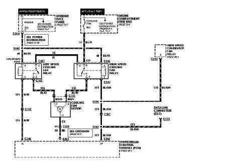
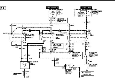
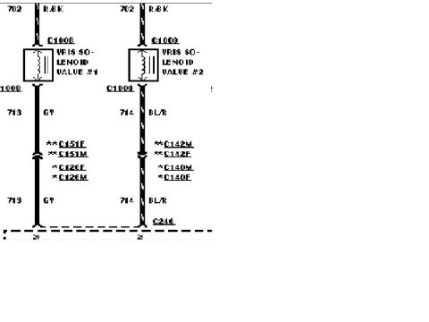
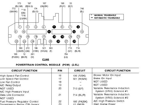
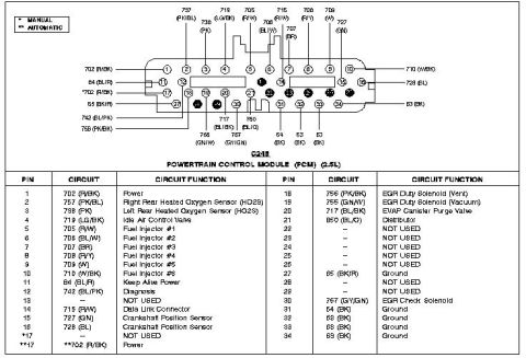
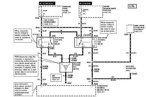
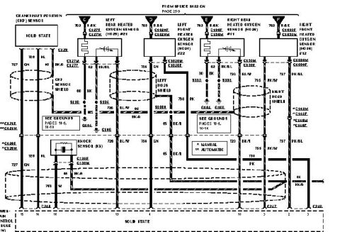
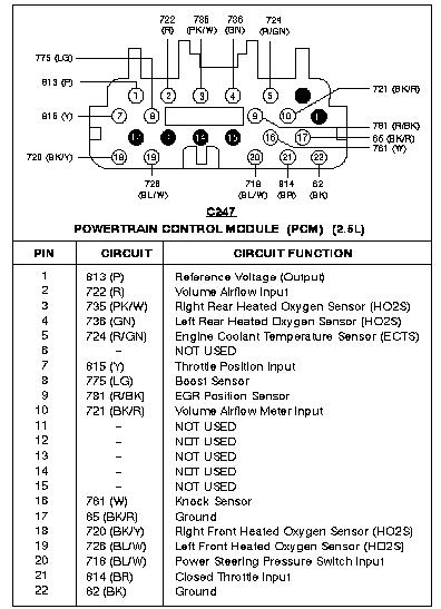









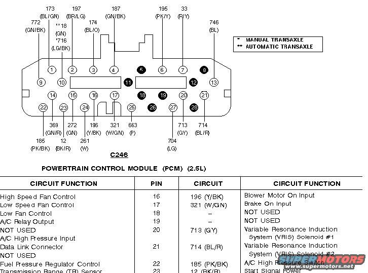
Powertrain control module connector C246 pinout with color-coded pins and circuit-function reference table.
Part of 1993-1997 Ford Probe Wiring Diagrams
This document is a partial page from a Ford wiring reference showing connector C246, the Powertrain Control Module (PCM) connector for the 2.5L engine (Ford Probe application per the uploader's album). The top portion is a pinout diagram of the 28-pin PCM connector with circuit numbers and wire color codes labeled for many terminals, including 173 (BL/GN), 197 (BR/LG), 187 (GN/BK), 195 (PK/Y), 33 (R/Y), 746 (BL), 772 (GN/BK), 18 (GN, automatic transaxle only), 716 (LG/BK, manual transaxle only), 174 (BL/O), 369 (GN/R), 272 (GN), 196 (Y/BK), 321 (W/GN), 663 (P), 713 (GY), 714 (BL/R), 185 (PK/BK), 12 (BK/R), 261 (W), and 704 (LG). A legend distinguishes manual (*) versus automatic (**) transaxle circuits. Below the diagram, a circuit function table lists pin assignments such as pin 16 High Speed Fan Control (196 Y/BK), pin 17 Low Speed Fan Control (321 W/GN), pin 20 VRIS Solenoid #1 (713 GY), pin 21 VRIS Solenoid #2 (714 BL/R), and pin 22 A/C High Pressure Switch (185 PK/BK). The table is cut off at the bottom of the scan, ending mid-way through the Transmission Range (TR) Sensor row.
Is this accurate? Sign in to help verify it.
Frequently asked questions
- What connector is shown in this diagram?
- Connector C246, the Powertrain Control Module (PCM) connector for the 2.5L engine.
- Which PCM pins control the cooling fans?
- Pin 16 is High Speed Fan Control (circuit 196, Y/BK wire), pin 17 is Low Speed Fan Control (circuit 321, W/GN wire), and there is also a Low Fan Control function listed at pin 18.
- Which pins operate the VRIS solenoids?
- Pin 20 (circuit 713, GY wire) is Variable Resonance Induction System (VRIS) Solenoid #1 and pin 21 (circuit 714, BL/R wire) is VRIS Solenoid #2.
- What do the * and ** symbols mean in the diagram?
- A single asterisk (*) marks circuits used with the manual transaxle (e.g., circuit 716 LG/BK), and a double asterisk (**) marks circuits used with the automatic transaxle (e.g., circuit 18 GN).
- What circuit and wire color connect to the A/C High Pressure Switch?
- Pin 22, circuit 185, with a PK/BK (pink/black) wire, connects to the A/C High Pressure Switch.






No comments yet.