1996 Ford Probe VRIS Solenoid Valve Wiring Diagram - C1008 C1009 C246 Pins 20/21
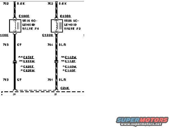
Wiring diagram showing the two VRIS solenoid valve circuits with color-coded wires and connector references.
This document is a cropped section of an automotive wiring diagram showing the circuits for two VRIS (Variable Resonance Induction System) solenoid valves, labeled VRIS Solenoid Valve #1 and VRIS Solenoid Valve #2. Both valves receive power on circuit 702 with a Red/Black (R/BK) wire. Valve #1 connects through connector C1008 and its output side runs on circuit 713 with a Gray (GY) wire; Valve #2 connects through connector C1009 and its output runs on circuit 714 with a Blue/Red (BL/R) wire. In-line connectors are shown along each wire: C151F/C151M and C126F/C126M (marked with ** and * respectively) on the Valve #1 circuit, and C142M/C142F and C140M/C140F on the Valve #2 circuit. Both circuits terminate at a module/connector boundary (with connector C246 labeled near the right circuit), entering at pins 20 and 21 respectively. A reader can learn the wire colors, circuit numbers, connector designations, and control-module pin assignments for the VRIS solenoid valves, which is useful for diagnosing intake resonance system faults or tracing the solenoid control wiring. The asterisk markings suggest connector applicability varies by variant, though no legend is visible in this crop.
Is this accurate? Sign in to help verify it.
Frequently asked questions
- What wire color powers the VRIS solenoid valves?
- Both VRIS Solenoid Valve #1 and Valve #2 are fed by circuit 702 with a Red/Black (R/BK) wire.
- What are the output wire colors and circuit numbers for the VRIS solenoids?
- Valve #1 output is circuit 713, Gray (GY); Valve #2 output is circuit 714, Blue/Red (BL/R).
- Which connectors are on the VRIS solenoid circuits?
- Valve #1 uses connector C1008 with in-line connectors C151F/C151M (**) and C126F/C126M (*). Valve #2 uses connector C1009 with in-line connectors C142M/C142F (**) and C140M/C140F (*). Connector C246 is labeled at the module boundary.
- Which control module pins do the VRIS solenoid wires go to?
- The Valve #1 circuit (713 GY) goes to pin 20 and the Valve #2 circuit (714 BL/R) goes to pin 21 at the dashed module/connector boundary.
Comments
More from this build








No comments yet.