1993 Ford Probe 2.5L A/C Condenser Fan & Clutch Circuit Wiring Diagram

Reference · 1993-1997 ProbeAll 65 wiring diagrams
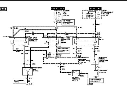
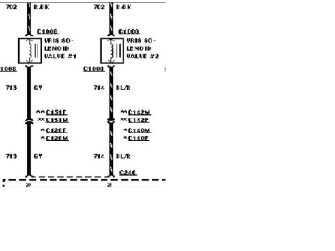
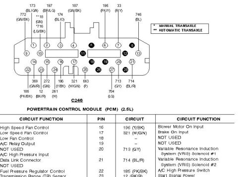
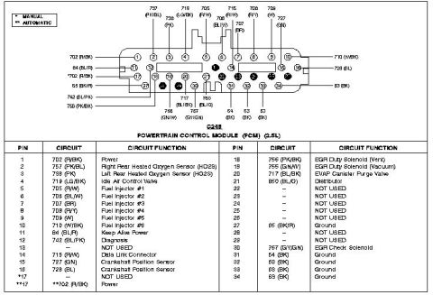
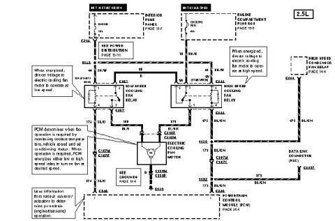









Wiring diagram for a 2.5L engine A/C clutch and condenser/cooling fan circuit showing relays, PCM, connectors and color-coded wires.
Part of 1993-1997 Ford Probe Wiring Diagrams
This document is a scanned automotive wiring diagram for the A/C condenser fan and A/C clutch circuit on a vehicle with a 2.5L engine (uploaded as a 1993 Ford Probe reference). Power comes from an AIR-COND 15A fuse in the interior fuse panel (hot in ACC or RUN) and an AIR-COND 40A fuse in the engine compartment fuse box (hot at all times). The diagram shows three relays, the Low Speed Condenser Fan Relay, High Speed Condenser Fan Relay, and A/C Relay, with their connector designations (C163, C154, C132) and wire circuits including 73 BL/BK, 88/89 GN/O, 197 BL/O, 199 BL/V, 171 PK, 173 BL/GN, 187 GN/BK, 191 BL/R, and 195 PK/Y. It traces circuits to the condenser fan motor (C100), the Powertrain Control Module (PCM) via connectors C246, C247, and C248, the A/C high pressure switch (C121), the A/C clutch thermal protection switch, and the A/C clutch field coil, with grounds at G103 and G102. Cross-references point to power distribution (pages 13-2, 13-4, 13-12), electric cooling fan (page 13-2), PCM pages (55-4, 55-5), and grounds (pages 10-2, 10-3, 10-4). A reader can identify relay pinouts, wire colors, connector numbers, and fuse ratings for diagnosing condenser fan or A/C clutch problems.
Is this accurate? Sign in to help verify it.
Frequently asked questions
- What fuses power the A/C condenser fan circuit on the 2.5L?
- A 15A AIR-COND fuse in the interior fuse panel (hot in ACC or RUN) and a 40A AIR-COND fuse in the engine compartment fuse box (hot at all times).
- What relays are in the 2.5L condenser fan / A/C circuit?
- The Low Speed Condenser Fan Relay (connector C163), the High Speed Condenser Fan Relay (connector C154), and the A/C Relay (connector C132).
- What wire colors feed the condenser fan motor?
- The fan motor (connector C100) receives circuit 199 BL/V from the low speed relay and 171 PK from the high speed relay, with a BK ground wire to ground G103.
- Which PCM pins are used in this A/C circuit?
- PCM pins 3N (197 BL/O via C248), 2P (173 BL/GN via C248), 1L (187 GN/BK via C246), and pin H (195 PK/Y via C247 to the A/C high pressure switch).
- How is the A/C clutch controlled per this diagram?
- The A/C relay sends 191 BL/R through C1003 to the A/C clutch thermal protection switch, then BK wire through C1013 to the A/C clutch field coil, which grounds at G102 (see grounds pages 10-2, 10-3).






No comments yet.