1993 Ford Probe Windshield Wiper & Washer Switch Wiring Diagram
Reference · 1993-1997 ProbeAll 65 wiring diagrams
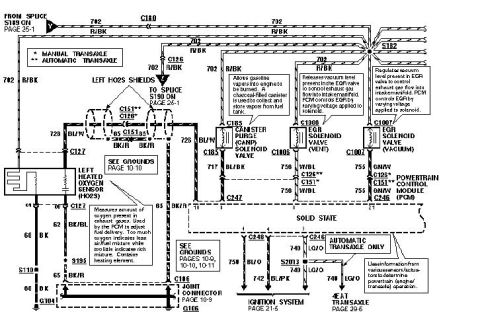
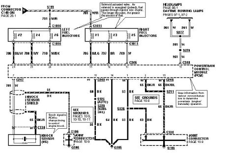
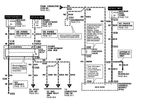
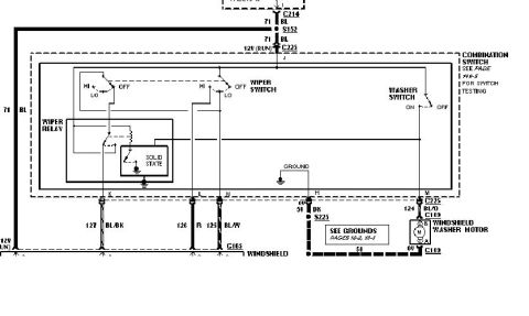









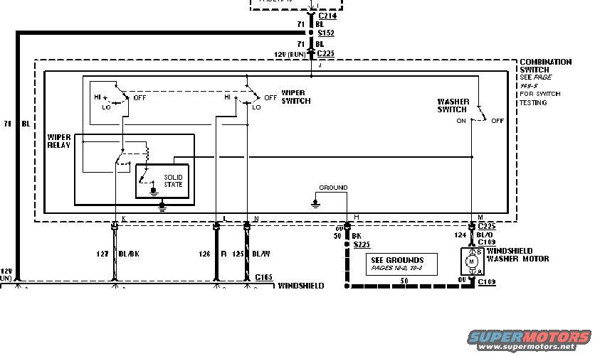
Wiring diagram showing the windshield wiper/washer circuit, including the wiper relay, combination switch, wiper motor and color-coded wires.
Part of 1993-1997 Ford Probe Wiring Diagrams
This is one page of a factory-style automotive wiring diagram covering the windshield wiper and washer circuit. It shows the combination switch assembly (with a note to 'SEE PAGE 149-5 FOR SWITCH TESTING'), which contains the wiper switch (HI/LO/OFF positions), the washer switch (ON/OFF), a wiper relay, and a solid-state module. Power enters the circuit on circuit 71 (BL, blue) at 12V in RUN, passing through connector C214, splice S152, and connector C225 to switch pin J. Output pins K, L, N, H, and M carry circuits 127 BL/BK, 126 R, 125 BL/W, 50 BK (ground, via splice S225), and 124 BL/O respectively. Circuit 124 BL/O feeds the windshield washer motor through connectors C225 and C109, with its ground returning on circuit 50. A callout directs the reader to 'SEE GROUNDS PAGES 10-2, 10-3.' Circuits 127, 126, and 125 pass through connector C165 toward the windshield wiper motor (continuing off-page). The diagram lets a reader identify wire colors, circuit numbers, connector and splice identifiers, and expected voltages (12V RUN, 0V at ground) for diagnosing wiper/washer problems.
Is this accurate? Sign in to help verify it.
Frequently asked questions
- What wire colors and circuit numbers are used in the Probe wiper switch circuit?
- Circuit 71 BL (blue) is the 12V RUN power feed; outputs are 127 BL/BK, 126 R, 125 BL/W, 50 BK (ground), and 124 BL/O (washer motor feed).
- Which connector pins on the combination switch serve the wiper/washer circuit?
- Pin J is the 12V (RUN) input; pins K, L, and N feed circuits 127, 126, and 125; pin H is ground (circuit 50 BK); pin M feeds the washer motor on circuit 124 BL/O.
- What connectors and splices are shown in the diagram?
- Connectors C214, C225, C165, and C109, plus splices S152 and S225 are identified.
- Where can switch testing information be found?
- The diagram notes 'SEE PAGE 149-5 FOR SWITCH TESTING' for the combination switch, and 'SEE GROUNDS PAGES 10-2, 10-3' for ground locations.
- What components are inside the combination switch assembly?
- The wiper switch (HI/LO/OFF), the washer switch (ON/OFF), a wiper relay, and a solid-state module are all shown within the combination switch.






No comments yet.