1993 Ford Probe Cooling Fan Circuit Wiring Diagram - Relays, PCM & Fuses
Reference · 1993-1997 ProbeAll 65 wiring diagrams
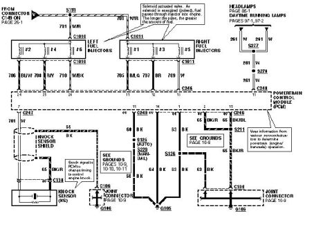
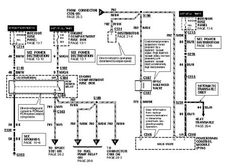
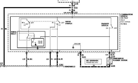
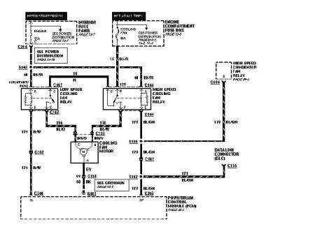
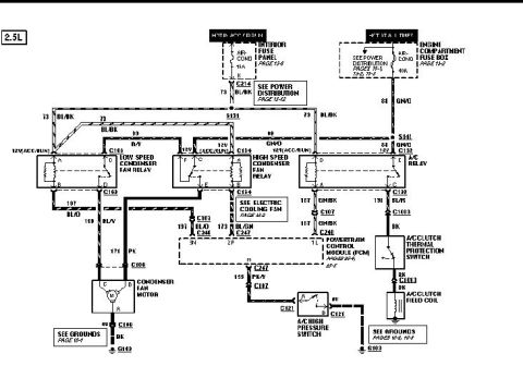
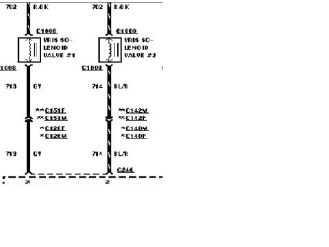
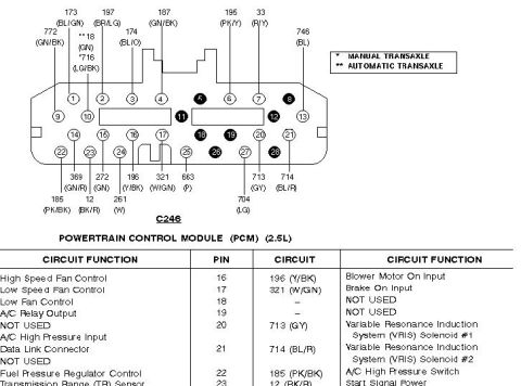









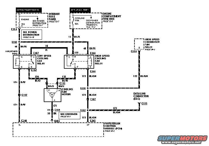
Wiring diagram of the engine cooling fan circuit showing low- and high-speed fan relays, fan motor, fuse boxes, PCM and color-coded wiring.
Part of 1993-1997 Ford Probe Wiring Diagrams
This document is a scanned automotive wiring diagram showing the engine cooling fan circuit, filed by the uploader for a 1993 Ford Probe. Power feeds come from two sources: a 15A ENGINE fuse in the interior fuse panel (hot in start or run, see page 13-7) and a 40A COOLING FAN fuse in the engine compartment fuse box (hot at all times, see page 13-3). These feeds pass through connector C214 and splice S142 on circuit 44 BK/W and circuit 15 BK/R to two relays: the Low Speed Cooling Fan Relay (connector C167) and the High Speed Cooling Fan Relay (connector C144). Relay outputs on circuits 194 BL/O and 176 BL/W run through connector C118 to the cooling fan motor (BR/O and BR/W leads), with the motor ground on circuit 50 BK to ground G103 (see grounds page 14-1). Relay control circuits 174 R/W and 173 BL/GN run through connectors C107, splices S188 and S192, to the Powertrain Control Module (PCM, page 25-1) at connectors C246 (pin 1L) and C247 (pin 2P). Circuit 173 BL/GN also connects to the High Speed Condenser Fan Relay (via C164, page 34-3) and the Data Link Connector (DLC, C135). Wire colors, circuit numbers, connector IDs, and relay pin letters are shown throughout.
Is this accurate? Sign in to help verify it.
Frequently asked questions
- What fuses power the cooling fan circuit on this diagram?
- Two fuses: the 15A ENGINE fuse in the interior fuse panel (hot in start or run, page 13-7) and the 40A COOLING FAN fuse in the engine compartment fuse box (hot at all times, page 13-3).
- What relays control the cooling fan?
- A Low Speed Cooling Fan Relay (connector C167) and a High Speed Cooling Fan Relay (connector C144). A High Speed Condenser Fan Relay (via C164, page 34-3) is also tied into circuit 173 BL/GN.
- What wire colors go to the cooling fan motor?
- Circuit 194 BL/O and circuit 176 BL/W feed connector C118, where the fan motor leads are BR/O (pin C) and BR/W (pin B). The ground side is circuit 50 BK to ground G103.
- Which PCM pins control the cooling fan relays?
- The relay control circuits run to the Powertrain Control Module at connector C246 pin 1L (circuit 174 R/W) and connector C247 pin 2P (circuit 173 BL/GN).
- Does the cooling fan circuit connect to the diagnostic connector?
- Yes: circuit 173 BL/GN branches through splice S192 to the Data Link Connector (DLC) at connector C135.






No comments yet.