1993-1994 Ford Probe PCM Power & Ground Wiring Diagram - ECU Page 1

Reference · 1993-1997 ProbeAll 65 wiring diagrams
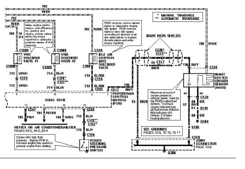
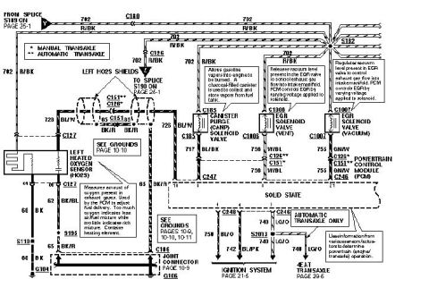
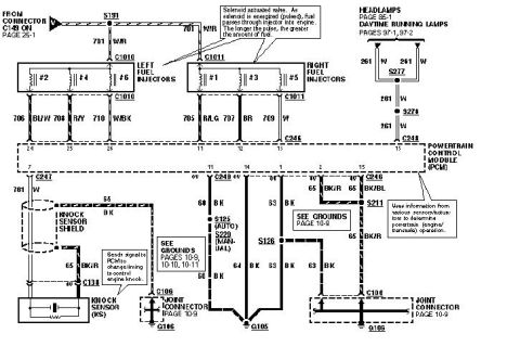
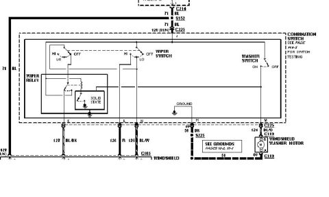
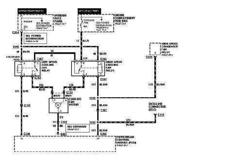
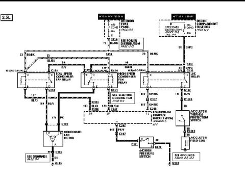
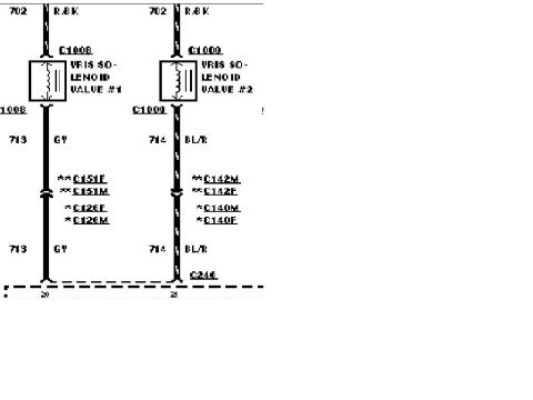









Ford wiring diagram showing power distribution to the PCM, IMRC solenoid valve and automatic transaxle with color-coded wires and connectors.
Part of 1993-1997 Ford Probe Wiring Diagrams
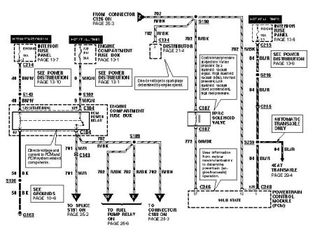
This is a scanned factory-style wiring diagram page covering the power supply and ground circuits for the Powertrain Control Module (PCM) system of a Ford Probe. It shows three power sources: the 15A ENGINE fuse in the interior fuse panel (hot in start or run, page 13-7), the 30A F/P INJ fuse in the engine compartment fuse box (hot at all times, page 13-1), and the 15A ROOM fuse in the interior fuse panel (hot at all times, page 13-6). The ENGINE fuse feeds the PCM power relay coil via circuit 40 BK/W, while the F/P INJ fuse feeds the relay contacts via circuit 9 W/GN. The relay output on circuit 702 R/BK splits at splice S189 to the distributor (C134), the fuel pump relay, splice S191, connector C180, and the FPRC solenoid valve (C187), which feeds PCM pin 37 via 772 GN/BK. The ROOM fuse supplies keep-alive power on circuit 84 BL/R to PCM connector C248 pin 1 and to the 4EAT transaxle (automatic only, page 29-4). Ground is via circuit 50 BK through splice S106 to ground G103. Explanatory callouts describe the PCM power relay, distributor voltage function, and FPRC solenoid fuel-pressure regulation behavior.
Is this accurate? Sign in to help verify it.
Frequently asked questions
- Which fuses power the PCM system on this diagram?
- Three fuses: the 15A ENGINE fuse in the interior fuse panel (hot in start or run, page 13-7), the 30A F/P INJ fuse in the engine compartment fuse box (hot at all times, page 13-1), and the 15A ROOM fuse in the interior fuse panel (hot at all times, page 13-6).
- What does the PCM power relay do?
- Per the callout, it directs voltage and current to the PCM and PCM system related components. It is located in the engine compartment fuse box and outputs on circuits 701 W/R and 702 R/BK.
- What wire color and circuit feeds the fuel pump relay and distributor?
- Circuit 702 R/BK from the PCM power relay splits at splice S189 to the fuel pump relay (page 25-6), splice S191 (page 25-2), connector C180 (page 25-3), and the distributor at C134 (page 21-4).
- How does the FPRC solenoid valve work according to this diagram?
- It controls fuel pressure at the injectors, varying pressure by a manifold vacuum signal: high manifold vacuum (idle) gives low fuel pressure; low manifold vacuum (hard acceleration) gives high fuel pressure. It connects to the PCM at connector C246 pin 37 via circuit 772 GN/BK.
- Where does the PCM ground circuit go?
- Circuit 50 BK runs through splice S106 (see Grounds, page 10-6) to ground point G103.






No comments yet.