1994 Ford Probe V6 PCM Wiring Diagram - Fuel Injectors, Knock Sensor, Grounds
Reference · 1993-1997 ProbeAll 65 wiring diagrams
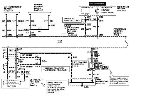
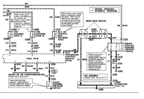
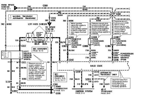
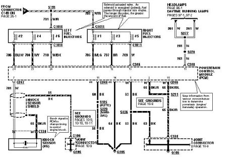
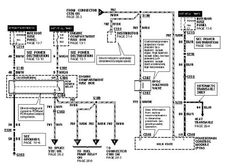
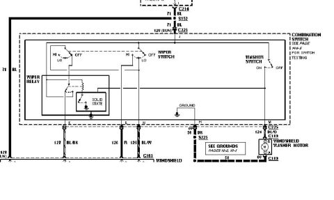
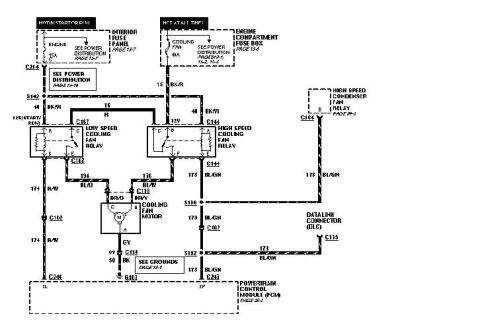
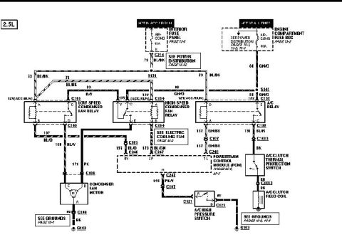









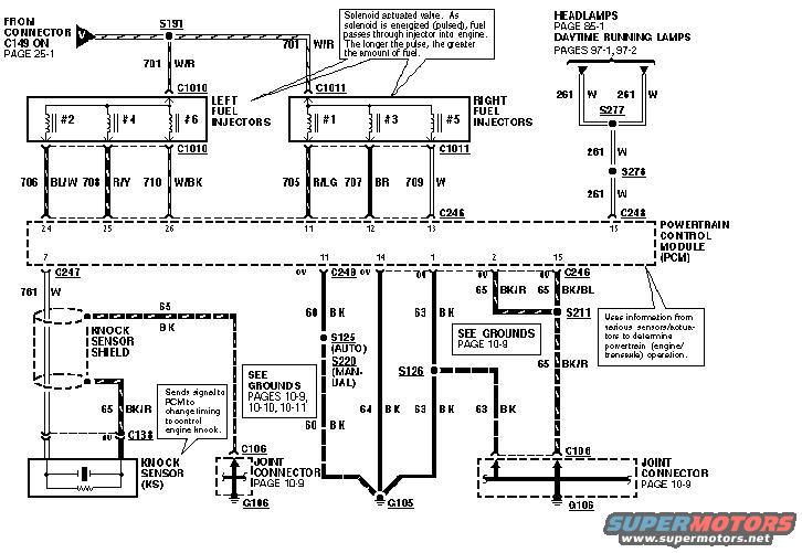
Ford wiring diagram showing left and right fuel injectors, the knock sensor and PCM connections with color-coded wires and grounds.
Part of 1993-1997 Ford Probe Wiring Diagrams
This scan is one page of a multi-page powertrain control module (PCM) wiring diagram, uploaded as "94 ecu page 2" for a Ford Probe. It shows the fuel injector circuits for a V6 engine: left fuel injectors #2, #4, #6 (through connector C1010, wires 706 BL/W, 708 R/Y, 710 W/BK to PCM pins 24-26) and right fuel injectors #1, #3, #5 (through connector C1011, wires 705 R/LG, 707 BR, 709 to PCM pins 27, 28, 12). Injector power comes from connector C149 (page 25-1) via circuit 701 W/R and splice S191. The knock sensor (KS) circuit with its shield is shown via connector C138 and circuit 761 W to PCM pin 7 (C247), with a note that it signals the PCM to retard timing to control engine knock. PCM ground circuits (60, 61, 63, 64 BK and 65 BK/R, 65 BK/BL) route through splices S125/S220 (auto/manual), S126 and S211 to grounds G105 and G106 via joint connectors C106. A branch to headlamps (page 85-1) and daytime running lamps (pages 97-1, 97-2) uses circuit 261 W through splices S277/S276 to C248 pin 15. Callouts explain injector pulse operation and PCM function.
Is this accurate? Sign in to help verify it.
Frequently asked questions
- What wire colors go to the fuel injectors on this Probe PCM diagram?
- Left injectors #2, #4, #6 use 706 BL/W, 708 R/Y and 710 W/BK to PCM pins 24, 25 and 26 via connector C1010. Right injectors #1, #3, #5 use 705 R/LG, 707 BR and 709 to PCM pins 27, 28 and 12 via connector C1011. Injector power feed is circuit 701 W/R from connector C149.
- How does the knock sensor connect to the PCM in this diagram?
- The knock sensor (KS) connects through connector C138 with a shielded circuit; signal wire 761 W goes to PCM pin 7 at connector C247, and the shield is grounded via 65 BK/(BK/R). A callout states it sends a signal to the PCM to change timing to control engine knock.
- Where do the PCM grounds go on this diagram?
- PCM ground wires 60, 61, 63 and 64 BK route through splices S125 (auto) / S220 (manual) and S126, and 65 BK/R / 65 BK/BL route through splice S211, all reaching grounds G105 and G106 via joint connectors C106 (see grounds pages 10-9, 10-10, 10-11).
- What does the diagram say about how the fuel injectors work?
- A callout explains: the injector is a solenoid actuated valve; as the solenoid is energized (pulsed), fuel passes through the injector into the engine, and the longer the pulse, the greater the amount of fuel.
- What circuit feeds the headlamp/daytime running lamp branch shown here?
- Circuit 261 W runs through splices S277 and S276 to PCM connector C248 pin 15, referencing Headlamps on page 85-1 and Daytime Running Lamps on pages 97-1 and 97-2.






No comments yet.