Home/
Registry/
Ford/
Bronco/
1992-1996/
1994 Ford Bronco/
Photo
supermotors.net/registry/media/896265
Hayden Electric Fan Controller Wiring Diagram - Ford Bronco EEC-IV Pin 57

Reference · 1992-1996 BroncoAll 411 wiring diagrams
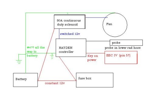

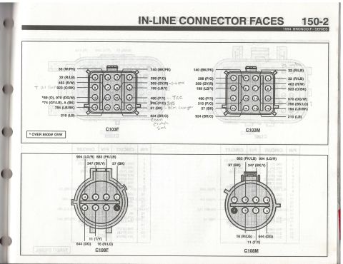
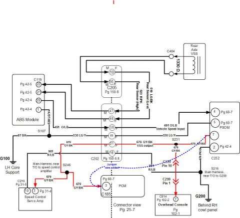
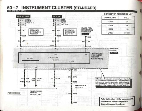
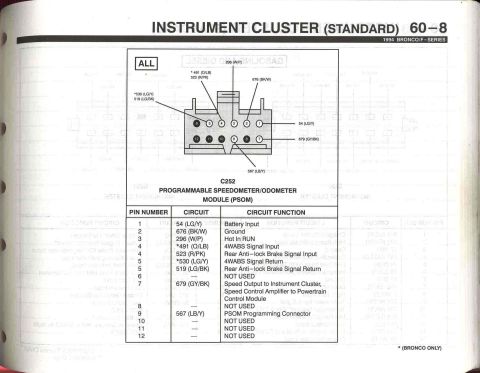
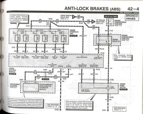
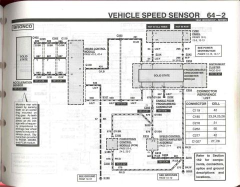
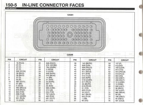









Electric cooling-fan wiring diagram showing battery, 80A solenoid, Hayden controller, temperature probe and EEC IV connection.
Part of 1992-1996 Ford Bronco Wiring Diagrams
This document is a simple hand-drawn wiring diagram showing how to wire a Hayden electric fan controller in a vehicle, uploaded to a 1994 Ford Bronco gallery. It shows an 80A continuous duty solenoid feeding switched 12v to the Hayden controller, which drives the electric fan. The controller's temperature probe is placed in the lower radiator hose ('probe in lower rad hose'). Key-on power for the controller is taken from EEC IV (pin 57). Constant 12v runs from the battery to the fuse box. A ground wire, annotated '#4?? all the way to battery' (suggesting 4-gauge cable), runs from the solenoid/fan circuit back to the battery, and ground symbols are shown at both the battery and the controller. Wire colors in the drawing are schematic (green for grounds/heavy cable, red for power feeds, blue label for switched 12v) rather than actual wire colors. A reader can learn the basic power, ground, trigger, and probe connections needed to install a Hayden adjustable fan controller with a relay/solenoid on a Ford EEC-IV equipped vehicle. No part numbers, fuse ratings (other than the 80A solenoid), or model years are stated in the document itself.
Is this accurate? Sign in to help verify it.
Frequently asked questions
- Where does the Hayden fan controller's temperature probe go?
- The diagram shows the probe installed in the lower radiator hose ('probe in lower rad hose').
- What size solenoid is used to power the fan?
- An 80A continuous duty solenoid is shown supplying switched 12v to the Hayden controller/fan circuit.
- Where does the key-on power for the controller come from?
- Key-on power is taken from EEC IV pin 57, shown wired to the Hayden controller.
- Where does constant 12v come from in this setup?
- Constant 12v runs from the battery to the fuse box, per the red wire labeled 'constant 12v'.
- How is the circuit grounded?
- A heavy ground wire (annotated '#4?? all the way to battery') runs back to the battery, with ground symbols shown at the battery and the Hayden controller.






No comments yet.