Home/
Registry/
Ford/
Bronco/
1992-1996/
1994 Ford Bronco/
Photo
supermotors.net/registry/media/911532
Ford Bronco Ignition Circuit Diagram - ICM, Coil, Distributor & EEC-IV PIP/SPOUT
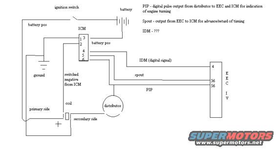
Ignition wiring diagram showing ignition switch, ICM, coil, distributor and EEC IV pin connections with PIP, SPOUT and IDM signals.
This document is a simplified hand-drawn wiring diagram of a Ford ignition circuit, showing how the ignition control module (ICM), ignition coil, distributor, and EEC-IV engine computer are interconnected. Battery positive power passes through the ignition switch to the ICM and coil. The ICM is drawn with six numbered pins (1, 2, 3, 4, 5, 6): pin 3 receives battery positive, pin 1/2 area connects to ground, and pins 4, 5, and 6 carry the IDM (digital signal), SPOUT, and PIP signals respectively toward the EEC-IV computer, which is shown with pins 4, 36, and 56. The coil is drawn with primary and secondary sides; the primary side receives a switched negative from the ICM, and the secondary side feeds the distributor. Text notes explain the key signals: PIP is a digital pulse output from the distributor to the EEC and ICM indicating the engine is turning; SPOUT is an output from the EEC to the ICM used to advance or retard ignition timing; the IDM signal's function is marked with question marks (unknown to the author). A reader can learn the basic signal flow of the TFI-style ignition system, which module drives coil primary switching, and which EEC-IV pins handle IDM, SPOUT, and PIP.
Is this accurate? Sign in to help verify it.
Frequently asked questions
- What is the PIP signal in this ignition diagram?
- PIP is a digital pulse output from the distributor to the EEC and ICM for indication of engine turning.
- What does the SPOUT signal do?
- SPOUT is an output from the EEC to the ICM for advance/retard of ignition timing.
- Which EEC-IV pins are shown for the ignition signals?
- The EEC-IV is shown with pins 4, 36, and 56 connecting to the IDM (digital signal), SPOUT, and PIP lines from the ICM.
- How is the ignition coil controlled in this circuit?
- The coil's primary side receives a switched negative from the ICM, while battery positive comes through the ignition switch; the secondary side feeds the distributor.
- Does the diagram explain the IDM signal?
- No. The note reads 'IDM - ???', indicating the author did not know its function, though it is labeled as a digital signal from the ICM to the EEC.
Comments
More from this build






No comments yet.