Ford TFI Ignition Module Wiring Schematic - Gray Distributor Mount (EEC Pins)
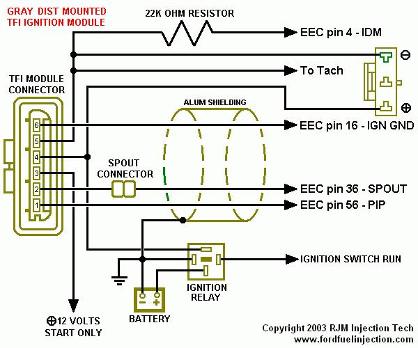
RJM wiring diagram for a gray distributor-mounted TFI ignition module: 6-pin connector, SPOUT connector, 22K-ohm IDM resistor and EEC pins 4/16/36/56, fed by ignition relay and battery.
This document is a wiring schematic for the gray distributor-mounted TFI (Thick Film Ignition) ignition module used on Ford EEC-controlled vehicles. It shows the six-pin TFI module connector and traces each pin's circuit: pin connections run through a 22K ohm resistor to EEC pin 4 (IDM - Ignition Diagnostic Monitor), to the tachometer, to the ignition coil (positive and negative terminals shown), to EEC pin 16 (IGN GND), through the SPOUT connector to EEC pin 36 (SPOUT), and to EEC pin 56 (PIP). The SPOUT and PIP wires are shown passing through aluminum shielding. Power distribution is illustrated via the ignition relay, which receives Ignition Switch Run and battery feeds, plus a separate 12-volt feed that is live during start only. The diagram is credited to RJM Injection Tech (copyright 2003) via fordfuelinjection.com. A reader can learn how the gray distributor-mounted TFI module interfaces with the EEC computer, coil, tach, and ignition switch/relay circuits, useful for diagnosing no-spark conditions, checking SPOUT and PIP signals, or verifying wiring when troubleshooting or replacing the TFI module on Ford trucks such as the Bronco.
Is this accurate? Sign in to help verify it.
Frequently asked questions
- Which EEC pins connect to the gray distributor-mounted TFI module?
- The diagram shows connections to EEC pin 4 (IDM, through a 22K ohm resistor), EEC pin 16 (IGN GND), EEC pin 36 (SPOUT, through the SPOUT connector), and EEC pin 56 (PIP).
- What resistor is in the IDM circuit to EEC pin 4?
- A 22K ohm resistor is shown between the TFI/coil circuit and EEC pin 4 - IDM.
- Which TFI wires are shielded?
- The SPOUT (EEC pin 36) and PIP (EEC pin 56) wires pass through aluminum shielding, which is tied to EEC pin 16 - IGN GND.
- How does the TFI module get power in this schematic?
- Power comes through the ignition relay (fed by Ignition Switch Run and the battery), plus a separate 12-volt feed labeled '12 VOLTS START ONLY'.
- Where does the tachometer signal come from?
- The 'To Tach' lead taps off the coil/IDM circuit at the top of the diagram, on the same line connected to the ignition coil negative side.
Comments
More from this build













No comments yet.