Home/
Registry/
Ford/
Bronco/
1978-1979/
1978 Ford Bronco/
Photo
supermotors.net/registry/media/914403
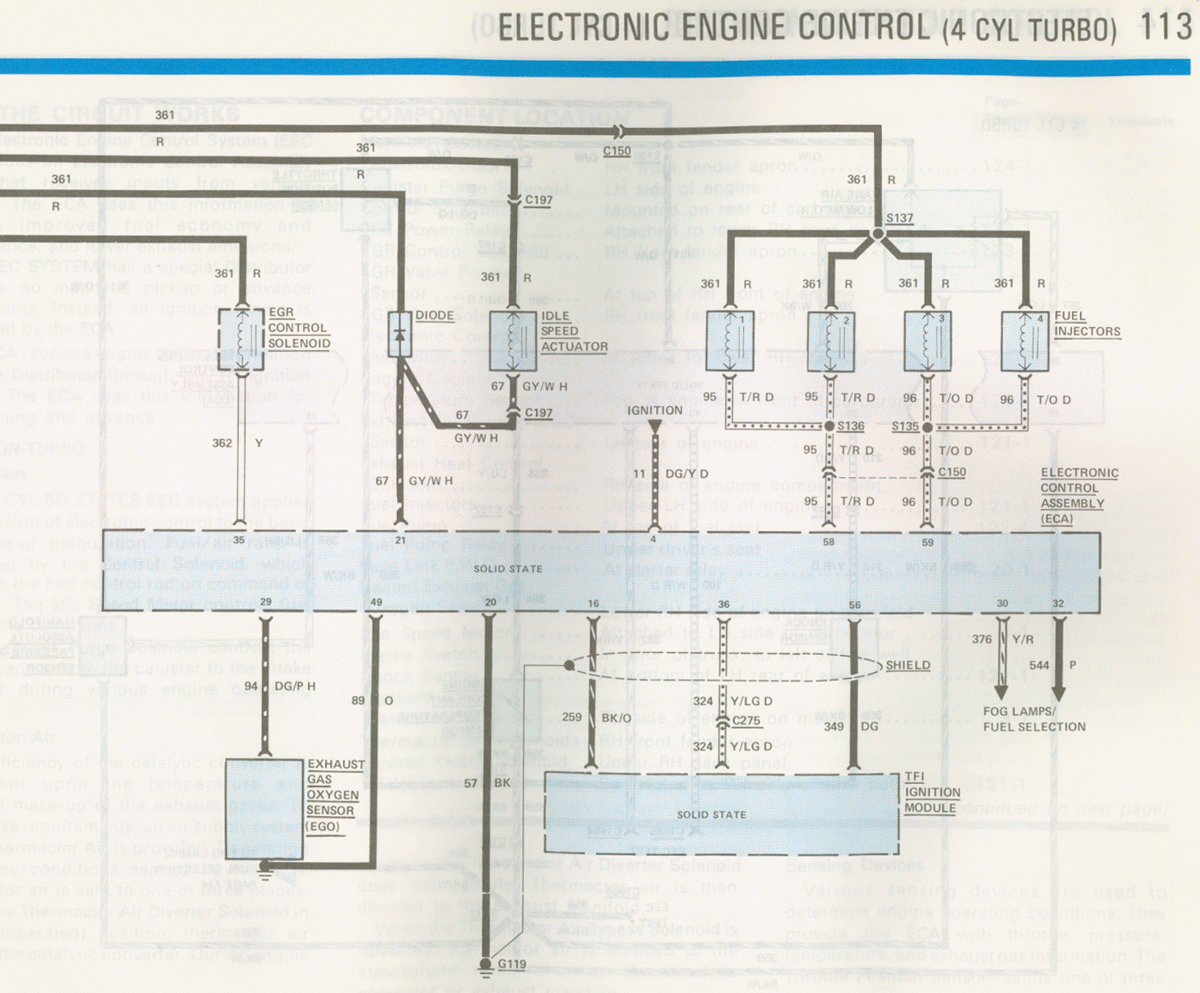
1986 Ford Mustang 2.3 Turbo EEC Wiring Diagram - ECA, Injectors, TFI (Page 113)
Reference · 1978-1979 BroncoAll 116 wiring diagrams
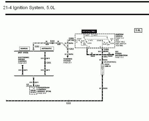
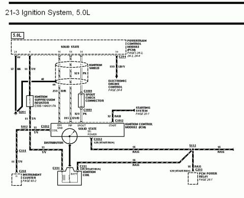
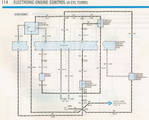
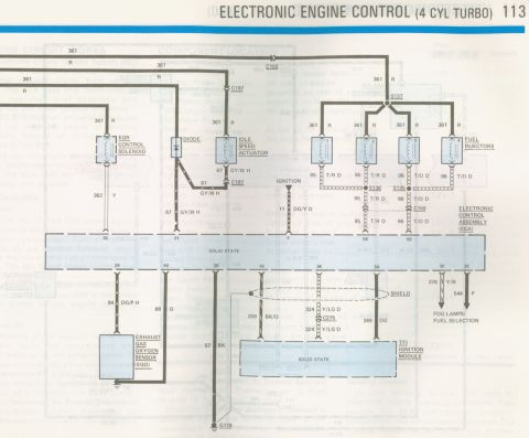
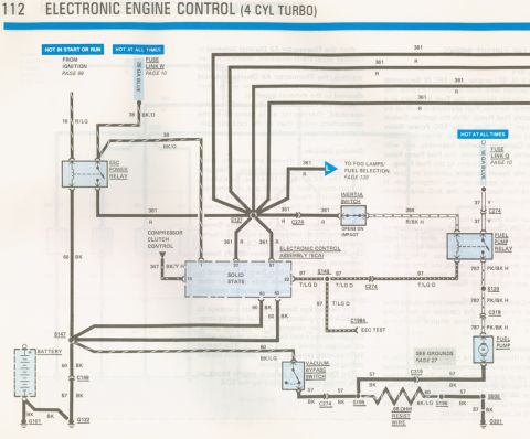
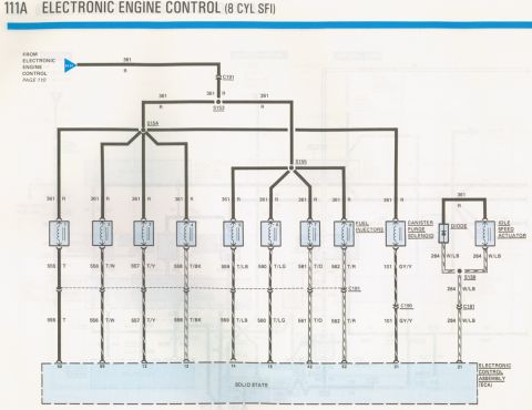
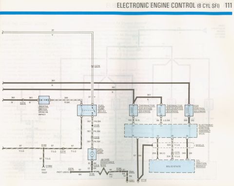
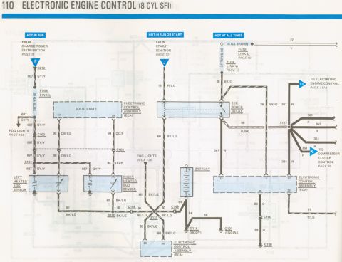
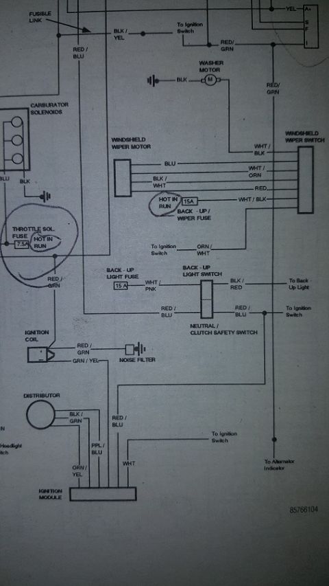
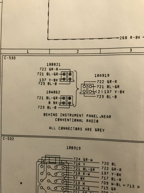
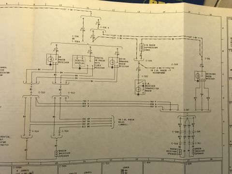



Wiring diagram of electronic engine control for a 4-cylinder turbo, showing fuel injectors, EGR solenoid, idle speed actuator, and exhaust gas oxygen sensor.
Part of 1978-1979 Ford Bronco Wiring Diagrams
This is page 113 of a Ford electrical/vacuum troubleshooting manual (EVTM) covering the Electronic Engine Control (EEC) system for the 4-cylinder turbo engine, from a 1986 Ford Mustang manual set based on companion pages. The wiring diagram shows the Electronic Control Assembly (ECA) and its connections: circuit 361 (Red) power feed through connectors C150/C197 and splice S137 to the EGR Control Solenoid, a diode, the Idle Speed Actuator, and four fuel injectors. Injector control wires are circuit 95 T/R (injectors 1-2, via splice S136, ECA pin 58) and circuit 96 T/O (injectors 3-4, via splice S135, ECA pin 59). Ignition feed is circuit 11 DG/Y to ECA pin 4. Other ECA pins shown: pin 35 (362 Y from EGR solenoid), pin 21 (67 GY/W from idle speed actuator), pin 29 (94 DG/P to the Exhaust Gas Oxygen sensor), pin 49 (89 O), pin 20 (57 BK ground to G119), pins 16/36/56 (259 BK/O, shielded 324 Y/LG through C275, and 349 DG to the TFI Ignition Module), and pins 30/32 (376 Y/R and 544 P to fog lamps/fuel selection). Faded text columns describe how the circuit works, component locations, and sensing devices.
This document covers 1986, which may differ from this 1978 Ford Bronco.
Is this accurate? Sign in to help verify it.
Frequently asked questions
- What circuit powers the fuel injectors on the 4-cylinder turbo EEC system?
- All four fuel injectors are fed by circuit 361, a Red wire, which branches through splice S137 and connector C150.
- What are the injector control wire colors and ECA pins?
- Injectors 1 and 2 use circuit 95 T/R (splice S136, ECA pin 58); injectors 3 and 4 use circuit 96 T/O (splice S135, ECA pin 59).
- Which ECA pins connect to the TFI Ignition Module?
- Pin 16 via circuit 259 BK/O, pin 36 via shielded circuit 324 Y/LG through connector C275, and pin 56 via circuit 349 DG.
- How is the Exhaust Gas Oxygen (EGO) sensor wired?
- The EGO sensor signal is circuit 94 DG/P to ECA pin 29, with circuit 89 O to pin 49; the sensor/ECA ground is 57 BK to ground G119 (ECA pin 20).
- What ignition feed does the ECA receive?
- Circuit 11 DG/Y from the ignition feeds ECA pin 4.






No comments yet.