Home/
Registry/
Ford/
Bronco/
1978-1979/
1978 Ford Bronco/
Photo
supermotors.net/registry/media/914404
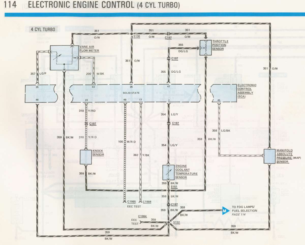
1986 Ford Mustang SVO 2.3 Turbo EEC Wiring Diagram - 4 Cyl Turbo Sensors (Pg 114)
Reference · 1978-1979 BroncoAll 116 wiring diagrams
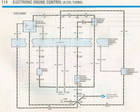
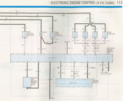
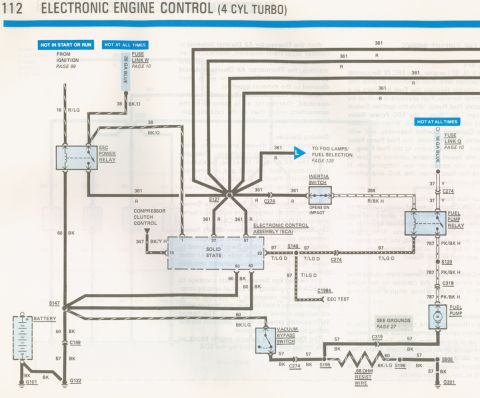
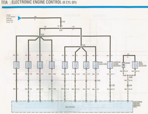
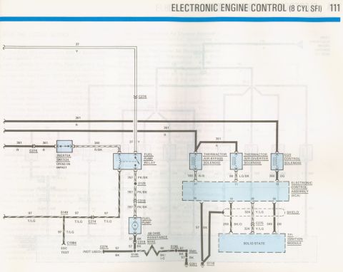
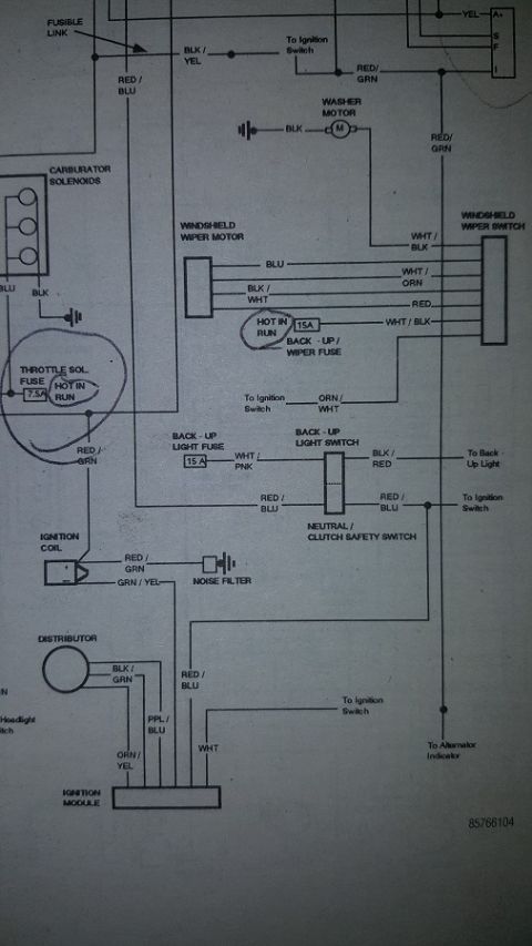
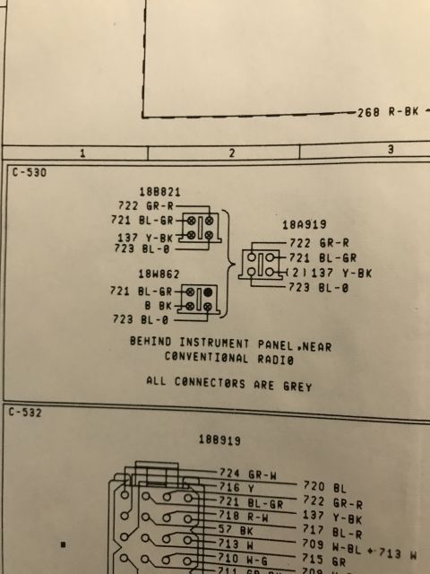
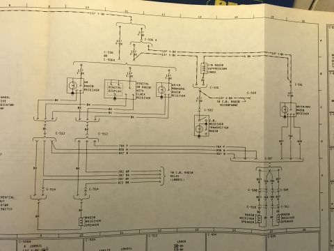
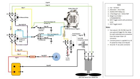

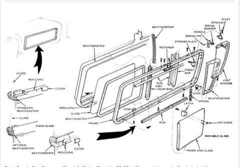
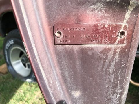


Wiring diagram of electronic engine control for a 4-cylinder turbo, showing the vane air flow meter, throttle position, knock, MAP, and coolant temperature sensors.
Part of 1978-1979 Ford Bronco Wiring Diagrams
This is page 114 of a Ford factory-style wiring diagram set titled "Electronic Engine Control (4 Cyl Turbo)." It shows the EEC (Electronic Engine Control) sensor wiring for a 4-cylinder turbocharged engine. The diagram details how the Electronic Control Assembly (ECA), a solid-state module, connects to the Vane Air Flow Meter, Throttle Position Sensor, Knock Sensor, Engine Coolant Temperature Sensor, Manifold Absolute Pressure (MAP) Sensor, and the EEC test connectors (C1985 and C1984). Circuit numbers and wire colors are given throughout: 351 O/W (sensor reference), 355 DG/LG (TPS signal), 357 LG/P and 200 W/BK (vane air flow meter), 310 Y/RD (knock sensor), 354 LG/Y (coolant temperature), 358 LG/BK (MAP sensor), 100 W/RD and 382 Y/BK (EEC test), and 359 BK/W (common signal return/ground running to splices S151 and S132). ECA connector pin numbers shown include 25, 46, 43, 23, 26, 48, 17, 47, 7, and 45. Connectors and splices identified include S130, C197, C1985, C1984, S151, and S132, plus a cross-reference marker "M" pointing to the fog lamps/fuel selection circuit on page 114. A reader can trace each engine sensor's signal and return wiring to the ECA.
Is this accurate? Sign in to help verify it.
Frequently asked questions
- What wire color and circuit number goes to the Throttle Position Sensor on the 4-cylinder turbo EEC system?
- The TPS receives circuit 351 O/W (orange/white) through connector C197 and circuit 355 DG/LG (dark green/light green), which runs to ECA pin 47.
- Which ECA pin connects to the Knock Sensor?
- ECA pin 23 connects to the Knock Sensor via circuit 310 Y/RD (yellow/red) through connector C197. The sensor's return is circuit 359 BK/W.
- What circuit feeds the Manifold Absolute Pressure (MAP) sensor?
- Circuit 358 LG/BK (light green/black) runs from ECA pin 45 to the MAP sensor, with 351 O/W reference and 359 BK/W return also shown at the sensor.
- What is the common ground/return circuit for the EEC sensors in this diagram?
- Circuit 359 BK/W (black/white) is the common return, running through splices S151 and S132, the C197 connector, the EEC test connector C1984, and to the fog lamps/fuel selection circuit on page 114.
- Which connectors are used for the EEC TEST?
- The EEC TEST uses connectors C1985 (circuit 100 W/RD from ECA pin 48) and C1984 (circuit 382 Y/BK from ECA pin 17, plus 359 BK/W).






No comments yet.