Home/
Registry/
Ford/
Bronco/
1978-1979/
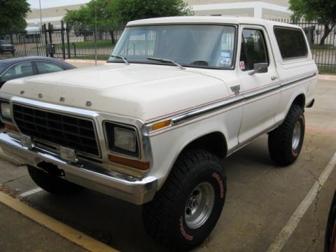
1978 Ford Bronco/
Photo
supermotors.net/registry/media/914406
1993 Ford Mustang 5.0L Ignition System Wiring Diagram - Page 21-4
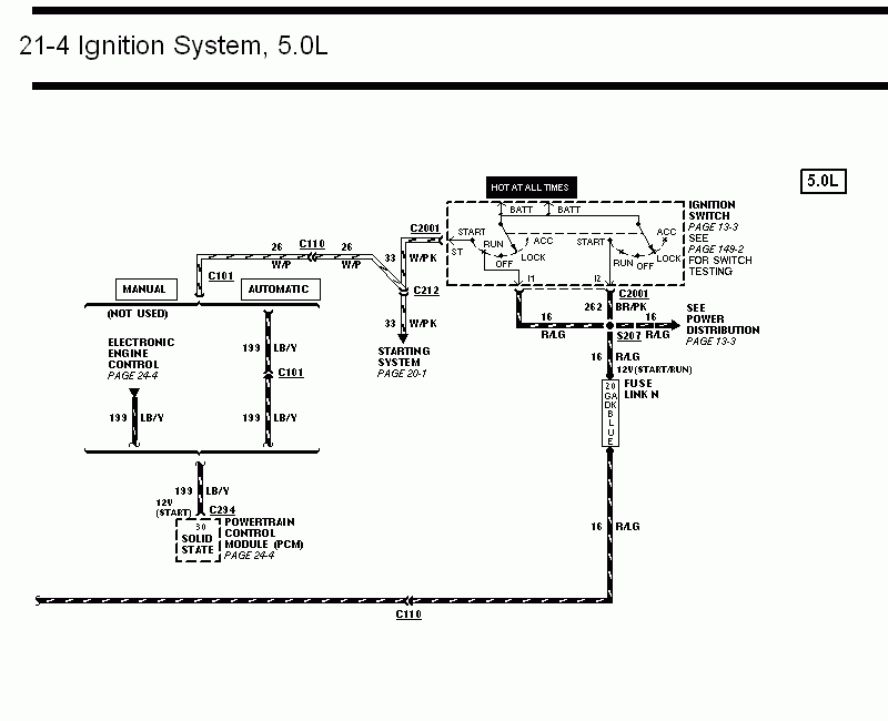
Wiring diagram of the 5.0L ignition system, showing the ignition switch, fuse link, PCM, and manual/automatic transmission start circuits.
This document is page 21-4 of a Ford factory-style wiring diagram set covering the Ignition System for the 5.0L engine (per the sibling files, a 1993 Ford Mustang manual). It shows the ignition switch (referenced to page 13-3, with switch testing on page 149-2) fed from battery power that is HOT AT ALL TIMES, with switch positions START, RUN, OFF, LOCK, and ACC and terminals I1 and I2. Circuit 262 BR/PK exits through connector C2001, and circuit 16 R/LG runs through splice S207 to Power Distribution (page 13-3), through Fuse Link N (20 GA dark blue) providing 12V in START/RUN. Circuit 33 W/PK goes via C212 to the Starting System (page 20-1). Circuit 26 W/P passes through connector C110, and circuit 199 LB/Y (12V in START) feeds the Electronic Engine Control / Powertrain Control Module (PCM) at connector C294 pin 30 (PCM detail on page 24-4). Manual and automatic transmission branches are shown, with the manual branch marked NOT USED. Readers can trace ignition-switch power distribution, wire circuit numbers, colors, connectors, and splices for the 5.0L ignition circuit.
This document covers 1993, which may differ from this 1978 Ford Bronco.
Is this accurate? Sign in to help verify it.
Frequently asked questions
- What wire circuit feeds the PCM 12V start signal in this diagram?
- Circuit 199 LB/Y (light blue/yellow) provides 12V in START to the Powertrain Control Module (PCM) at connector C294, pin 30.
- What fuse link protects the ignition run/start feed?
- Fuse Link N, a 20 gauge dark blue fuse link, is in the 16 R/LG circuit that provides 12V in START/RUN.
- Which circuit goes to the starting system?
- Circuit 33 W/PK (white/pink) runs through connectors C2001 and C212 to the Starting System, shown on page 20-1.
- Where is ignition switch testing covered?
- The diagram notes to see page 149-2 for ignition switch testing; the switch itself is detailed on page 13-3.
- What connectors are shown in this 5.0L ignition circuit?
- Connectors C110, C101, C2001, C212, and C294 are shown, along with splice S207.
Comments
More from this build













No comments yet.