Home/
Registry/
Ford/
Bronco/
1978-1979/
1978 Ford Bronco/
Photo
supermotors.net/registry/media/914407
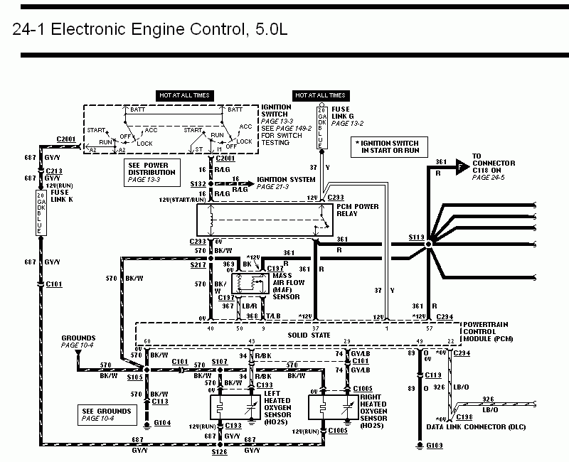
1993 Ford Mustang 5.0L EEC Wiring Diagram 24-1 - PCM, MAF & O2 Sensor Circuits
Reference · 1978-1979 BroncoAll 116 wiring diagrams
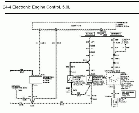
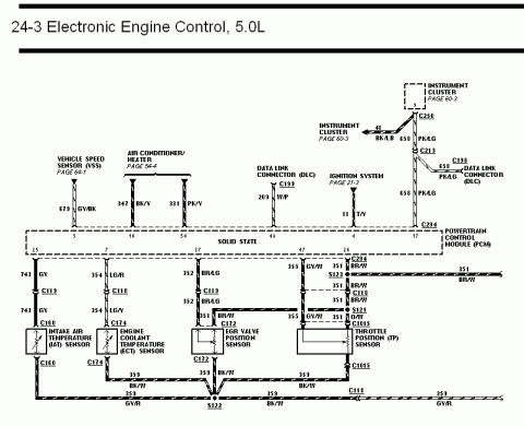
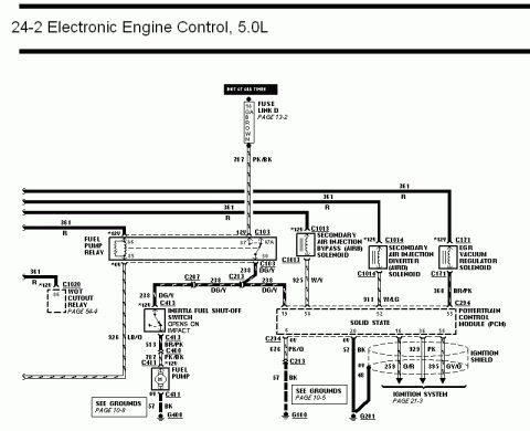
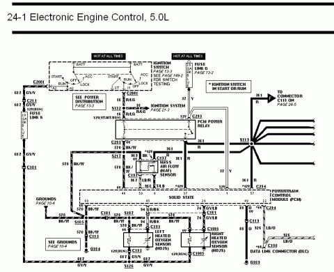
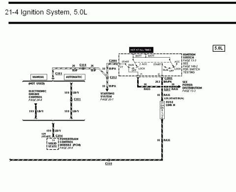
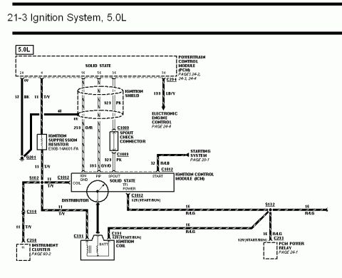
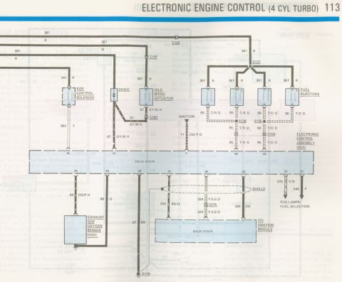
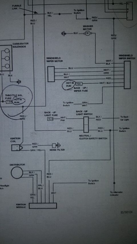
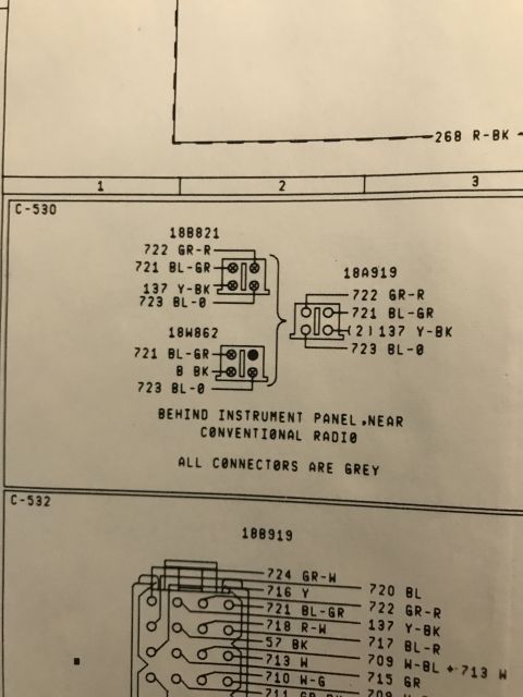
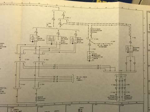
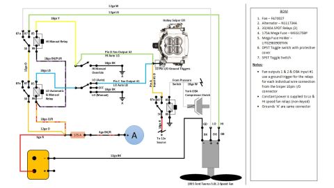

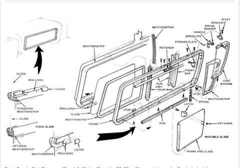


Wiring diagram of 5.0L electronic engine control, showing the PCM power relay, mass air flow sensor, heated oxygen sensors, and data link connector.
Part of 1978-1979 Ford Bronco Wiring Diagrams
This document is page 24-1 of a Ford factory-style wiring diagram set covering the Electronic Engine Control (EEC) system for a 5.0L engine. It shows power distribution from the ignition switch (hot at all times, with BATT, START, RUN, OFF, ACC, LOCK positions) through Fuse Link G (20 GA dark blue) and Fuse Link K (20 GA dark blue), feeding the PCM Power Relay via circuit 16 R/LG and circuit 37 Y. Circuit 361 R distributes switched power from the relay to the PCM, the Mass Air Flow (MAF) sensor, and to connector C118 on page 24-5. The diagram details wiring for the MAF sensor (circuits 363 BK, 361 R, 367 LB/R, 368 T/LB at connector C197), the left and right Heated Oxygen Sensors (HO2S) with circuits 94 R/BK, 570 BK/W, and 687 GY/Y, and the Data Link Connector (DLC) via circuits 89 O and 326 LB/O through connectors C113 and C198. Ground paths are shown through S105, S107, S217, C113, G104, G109, and S126, with cross-references to Grounds (page 10-4), Power Distribution (page 13-3), the Ignition System (page 21-3), and switch testing (page 149-2). PCM pin numbers 40, 50, 9, 37, 1, and 57 are identified at connector C294.
Is this accurate? Sign in to help verify it.
Frequently asked questions
- What does wiring diagram page 24-1 cover?
- It covers the Electronic Engine Control (EEC) system for the 5.0L engine, including the ignition switch feed, PCM power relay, powertrain control module (PCM), mass air flow (MAF) sensor, left and right heated oxygen sensors (HO2S), and the data link connector (DLC).
- What wire circuit powers the PCM power relay?
- The relay is fed by circuit 16 R/LG (red/light green) from the ignition switch (12V in START/RUN) and by circuit 37 Y (yellow) from Fuse Link G, a 20 gauge dark blue fuse link. The relay output is circuit 361 R (red).
- What are the MAF sensor wire colors on this diagram?
- At connector C197 the MAF sensor uses circuit 363 BK (*12V), 361 R, 367 LB/R, 368 T/LB, and a BK/W ground wire.
- What circuits connect the heated oxygen sensors?
- Both the left and right HO2S use circuit 94 R/BK (signal to the PCM), 570 BK/W (0V ground), and 687 GY/Y (12V in RUN, fed through Fuse Link K). The left sensor connects at C133 and the right at C1005.
- Which circuits go to the Data Link Connector (DLC)?
- Circuit 89 O (orange) runs to ground G109, and circuit 326 LB/O (light blue/orange) runs through connector C198 to the DLC, with connections at C113 and C294 on the PCM side.






No comments yet.