Home/
Registry/
Ford/
Bronco/
1978-1979/
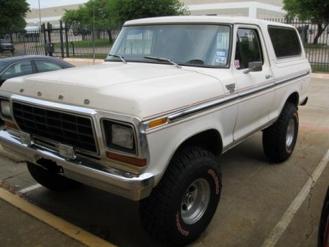
1978 Ford Bronco/
Photo
supermotors.net/registry/media/914410
1993 Ford Mustang 5.0L EEC Wiring Diagram 24-4 - PCM, BARO, Neutral Switch
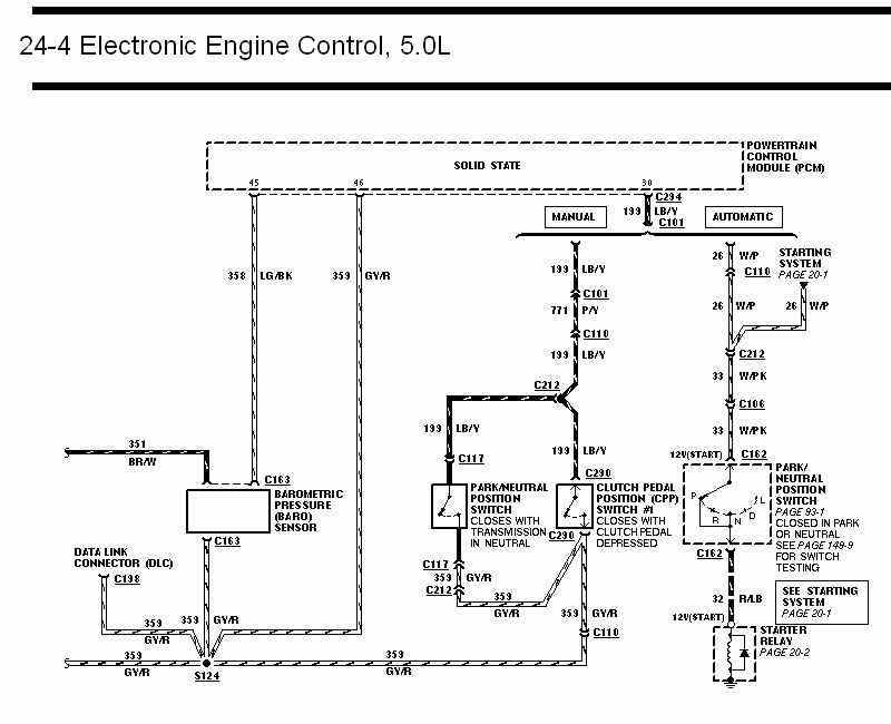
Wiring diagram of 5.0L electronic engine control, showing the barometric pressure sensor, park/neutral switch, clutch pedal position switch, and starter relay.
This is page 24-4 of a Ford factory wiring diagram set covering the Electronic Engine Control (EEC) system for the 5.0L engine. It shows the Powertrain Control Module (PCM, solid state) pins 45, 46, and 30 and their circuits: 358 LG/BK, 359 GY/R, and 199 LB/Y. The diagram splits into MANUAL and AUTOMATIC transmission branches from PCM pin 30. The manual branch runs circuit 199 LB/Y (with 771 P/Y through C110) to the Park/Neutral Position Switch (closes with transmission in neutral) via C117 and the Clutch Pedal Position (CPP) Switch #1 (closes with clutch pedal depressed) via C290. The automatic branch runs circuits 26 W/P and 33 W/PK through connectors C110, C212, C106, and C162 to the Park/Neutral Position Switch (P, R, N, D, L; closed in Park or Neutral, see page 93-1 and 149-9 for testing), then via 32 R/LB to the starter relay (page 20-2) and starting system (page 20-1). Also shown are the Barometric Pressure (BARO) Sensor (circuits 351 BR/W and 359 GY/R via C163) and the Data Link Connector (DLC, C198), with grounds converging at splice S124 on circuit 359 GY/R.
This document covers 1993, which may differ from this 1978 Ford Bronco.
Is this accurate? Sign in to help verify it.
Frequently asked questions
- What PCM pins are shown on this 5.0L EEC diagram?
- Pin 45 (circuit 358 LG/BK), pin 46 (circuit 359 GY/R), and pin 30 (circuit 199 LB/Y via C294/C101).
- What wire color feeds the Barometric Pressure (BARO) sensor?
- Circuit 351 BR/W feeds the BARO sensor, with circuit 359 GY/R through connector C163 going to ground splice S124.
- When does the Clutch Pedal Position (CPP) Switch #1 close?
- The diagram states it closes with the clutch pedal depressed; it connects via C290 on circuit 199 LB/Y with 359 GY/R output to C110.
- When is the Park/Neutral Position Switch closed on automatic models?
- It is closed in Park or Neutral; the diagram references page 93-1 and page 149-9 for switch testing.
- Where does circuit 32 R/LB go?
- From the Park/Neutral Position Switch (C162) through circuit 32 R/LB to the starting system (page 20-1) and starter relay (page 20-2), labeled 12V(START).
Comments
More from this build













No comments yet.