Home/
Registry/
Ford/
Bronco/
1978-1979/
1978 Ford Bronco/
Photo
supermotors.net/registry/media/914409
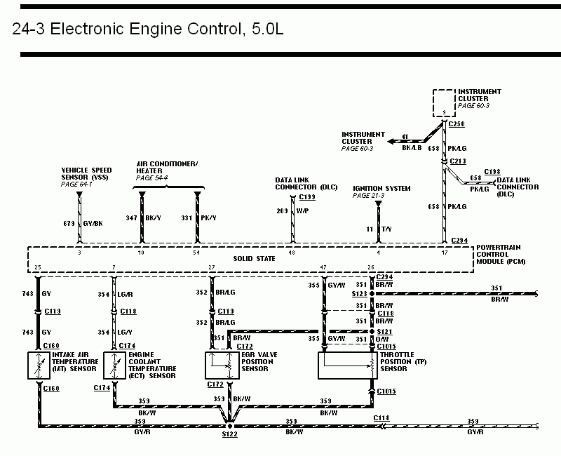
1993 Ford Mustang 5.0L EEC Wiring Diagram 24-3 - PCM Sensor Circuits & Pinout
Reference · 1978-1979 BroncoAll 116 wiring diagrams
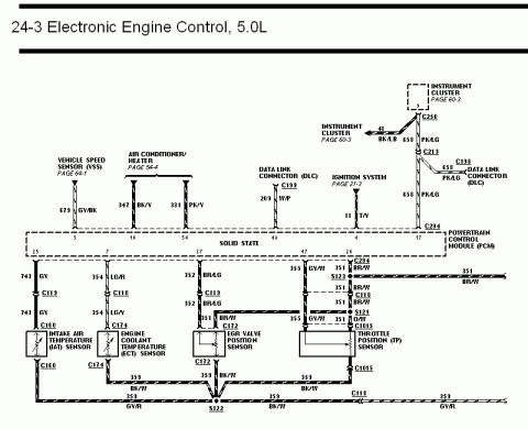
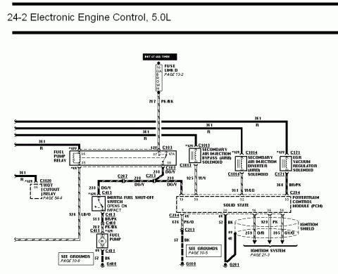
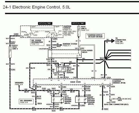
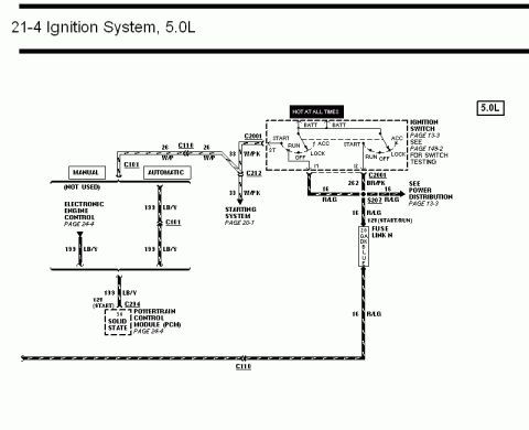
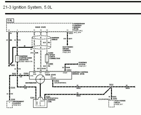
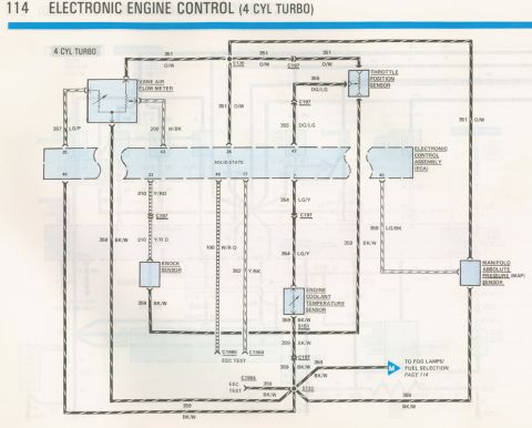
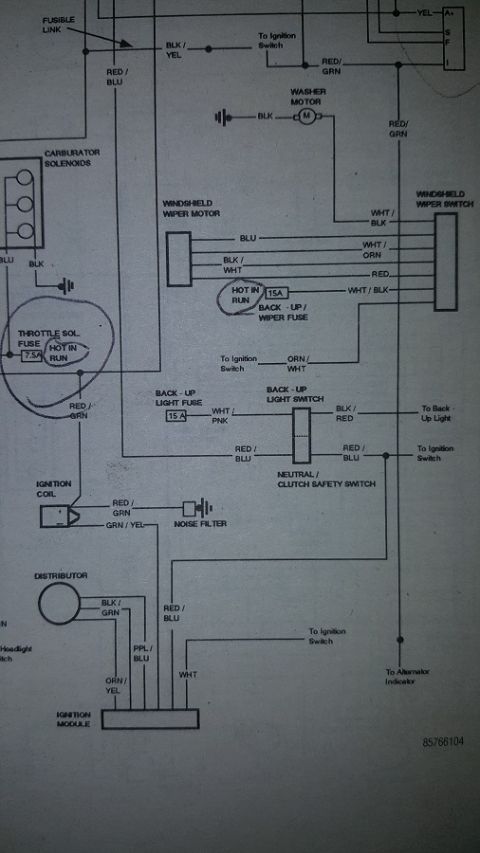
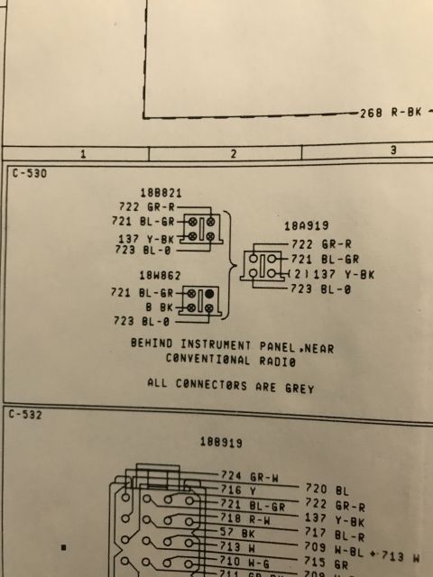
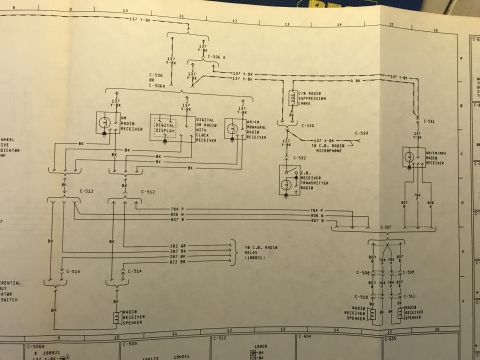
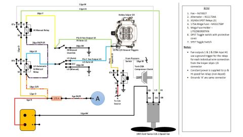

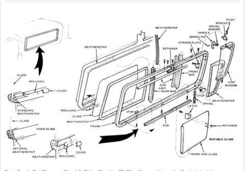
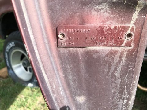


Wiring diagram of 5.0L electronic engine control, showing the VSS, IAT, ECT, EGR valve position, and throttle position sensors with the PCM and cluster.
Part of 1978-1979 Ford Bronco Wiring Diagrams
This document is page 24-3 of a factory-style wiring diagram set covering the Electronic Engine Control (EEC) system for a 5.0L engine. It centers on the Powertrain Control Module (PCM), shown as a dashed "solid state" box, and maps its connections to major sensors and subsystems. Top-side circuits include the Vehicle Speed Sensor (VSS, circuit 679 GY/BK to pin 3, cross-referenced to page 64-1), Air Conditioner/Heater (347 BK/Y to pin 10 and 331 PK/Y to pin 54, page 54-4), Data Link Connector (209 W/P to pin 48 via C193), Ignition System (11 T/Y to pin 4, page 21-3), and Instrument Cluster (658 PK/LG through C250, C213, C294 to pin 17, plus circuit 41 BK/LB, page 60-3). Bottom-side circuits detail the Intake Air Temperature (IAT), Engine Coolant Temperature (ECT), EGR Valve Position, and Throttle Position (TP) sensors, with signal circuits 743 GY, 354 LG/R, 352 BR/LG, and 355 GY/W, a shared reference circuit 351 BR/W through splices S123 and S121, and a common sensor ground circuit 359 BK/W joining at splice S122 before continuing as 359 GY/R. All connector numbers (C113, C118, C160, C172, C174, C1015, etc.) and PCM pin numbers are labeled, making the page useful for diagnosing sensor and PCM wiring faults.
Is this accurate? Sign in to help verify it.
Frequently asked questions
- Which PCM pin does the Throttle Position (TP) sensor signal connect to?
- The TP sensor signal is circuit 355 GY/W, which connects to PCM pin 47 through connector C1015.
- What wire color and circuit number is the Vehicle Speed Sensor (VSS) input to the PCM?
- The VSS input is circuit 679 GY/BK, connecting to PCM pin 3. The VSS itself is detailed on page 64-1.
- Where do the sensor grounds for the IAT, ECT, EGR and TP sensors join?
- All four sensors use circuit 359 BK/W for ground, joining at splice S122, then continuing as 359 GY/R and through connector C118.
- What circuit provides the shared reference voltage to the EGR and TP position sensors?
- Circuit 351 BR/W from PCM pin 26 runs through C294, splice S123, C118 and splice S121 (becoming 351 O/W into C1015) to feed the EGR valve position and throttle position sensors.
- Which PCM pin connects to the Data Link Connector (DLC)?
- The DLC connects to PCM pin 48 via circuit 209 W/P through connector C193; a second DLC connection (658 PK/LG) branches from C213 at connector C198.






No comments yet.