Home/
Registry/
Ford/
Bronco/
1978-1979/
1978 Ford Bronco/
Photo
supermotors.net/registry/media/914408
1993 Ford Mustang 5.0L EEC Wiring Diagram 24-2 - Fuel Pump Relay, PCM, EGR
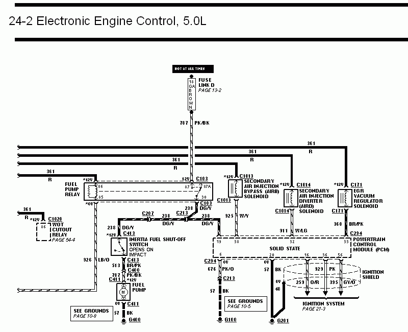
Wiring diagram of 5.0L electronic engine control, showing the fuel pump relay, inertia switch, secondary air injection solenoids, and EGR vacuum regulator.
This document is page 24-2 of an electronic engine control (EEC) wiring diagram for a Ford 5.0L engine, apparently from a 1993 Ford Mustang wiring manual. It traces power distribution from a Hot At All Times feed through Fuse Link D (18 GA Brown, page 13-2) via circuit 787 PK/BK to the fuel pump relay. The diagram shows the fuel pump relay (pins 30, 85, 86, 87, 87A), the WOT cutout relay (connector C1020, page 54-4), the Secondary Air Injection Bypass (AIRB) solenoid (C1013), Secondary Air Injection Diverter (AIRD) solenoid (C1014), and the EGR vacuum regulator solenoid (C171), all fed by circuit 361 R. Circuit 238 DG/Y runs from the fuel pump relay through connectors C207 and C213 to the inertia fuel shut-off switch (C413, opens on impact), then via 787 PK/BK to the fuel pump (C411), grounded at G400 (grounds page 10-8). The Powertrain Control Module (PCM, connector C294) is shown with pins 19, 38, 6, 20, 16, 36, and 56, including PCM ground circuits 676 PK/O and 57 BK to grounds G100 and G201, plus ignition-related circuits 929 PK, 259 O/R, and 395 GY/O routed through the ignition shield to the ignition system (page 21-3). Wire circuit numbers and color codes are given throughout.
This document covers 1993, which may differ from this 1978 Ford Bronco.
Is this accurate? Sign in to help verify it.
Frequently asked questions
- What circuit feeds the fuel pump relay on the 5.0L EEC system?
- Circuit 787 PK/BK, fed from a Hot At All Times source through Fuse Link D (18 GA Brown, shown on page 13-2).
- What wire runs from the fuel pump relay to the inertia fuel shut-off switch?
- Circuit 238 DG/Y, passing through connectors C207 and C213 to the inertia switch at C413, which opens on impact.
- What connector is the EGR vacuum regulator solenoid on and what is its signal wire?
- The EGR vacuum regulator solenoid uses connector C171 with signal circuit 360 BR/PK going to the PCM.
- Where are the PCM grounds shown on this diagram?
- PCM pin 6 grounds via 676 PK/O and 57 BK to G100 (see grounds page 10-5), and pin 20 grounds via 57 BK to G201. The fuel pump grounds via 57 BK at G400 (grounds page 10-8).
- What circuits connect the PCM to the ignition system?
- Circuits 929 PK, 259 O/R, and 395 GY/O run from PCM pins 16, 36, and 56 through the ignition shield to the ignition system (page 21-3).
Comments
More from this build














No comments yet.