Home/
Registry/
Ford/
Bronco/
1978-1979/
1978 Ford Bronco/
Photo
supermotors.net/registry/media/914411
1993 Ford Mustang 5.0L EEC Wiring Diagram 24-5 - Fuel Injectors, IAC & CANP
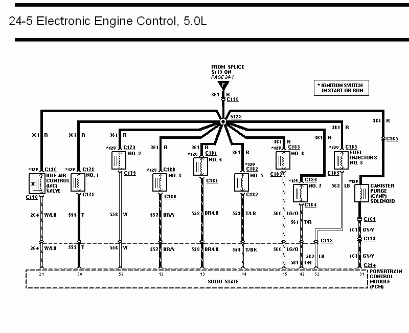
Wiring diagram of 5.0L electronic engine control, showing the eight fuel injectors, idle air control valve, and canister purge solenoid wired to the PCM.
This document is page 24-5 of a Ford wiring diagram set covering the Electronic Engine Control system for the 5.0L engine (the filename and companion pages indicate a 1993 Ford Mustang manual). It shows ignition-switched 12V power (active in START or RUN) arriving from splice S113 (referenced to page 24-1) on circuit 361, a red wire, passing through connector C118 to splice S128. From S128, red 361 wires feed the Idle Air Control (IAC) valve (connector C130), fuel injectors No. 1 through No. 8 (connectors C178-C185), and the Canister Purge (CANP) solenoid via connector C165. Each device's control (ground) side runs to a numbered pin on the solid-state Powertrain Control Module (PCM): IAC on wire 264 W/LB to pin 21; injectors 1-8 on wires 555 T (pin 58), 556 W (pin 59), 557 BR/Y (pin 12), 558 BR/LB (pin 13), 559 T/LB (pin 14), 560 LG/O (pin 15), 561 T/R (pin 42), and 562 LB (pin 52); and the CANP solenoid on wire 101 GY/Y through C119 and C294 to pin 31. A reader can identify wire colors, circuit numbers, connector IDs, and PCM pin assignments for injector and emissions-solenoid diagnosis.
Is this accurate? Sign in to help verify it.
Frequently asked questions
- What PCM pins do the fuel injectors connect to on the 5.0L EEC system?
- Injector No. 1 goes to pin 58 (wire 555 T), No. 2 to pin 59 (556 W), No. 3 to pin 12 (557 BR/Y), No. 4 to pin 13 (558 BR/LB), No. 5 to pin 14 (559 T/LB), No. 6 to pin 15 (560 LG/O), No. 7 to pin 42 (561 T/R), and No. 8 to pin 52 (562 LB).
- Where do the injectors and IAC valve get their 12V power?
- From splice S113 (shown on page 24-1) through wire 361 R and connector C118 to splice S128, which distributes 361 R to each injector, the IAC valve, and the CANP solenoid. The 12V is present with the ignition switch in START or RUN.
- What wire and PCM pin does the Idle Air Control (IAC) valve use?
- The IAC valve (connector C130) uses wire 264 W/LB, which connects to PCM pin 21.
- How is the Canister Purge (CANP) solenoid wired?
- It receives 361 R power through connector C165, and its control wire 101 GY/Y runs through C165, C119, and C294 to PCM pin 31.
- What connectors are used for the eight fuel injectors?
- C178 (No. 1), C179 (No. 2), C180 (No. 3), C181 (No. 4), C182 (No. 5), C183 (No. 6), C184 (No. 7), and C185 (No. 8).
Comments
More from this build














No comments yet.