1994 Ford Probe PCM Wiring Diagram - HO2S, CANP & EGR Solenoid Circuits
Reference · 1993-1997 ProbeAll 65 wiring diagrams
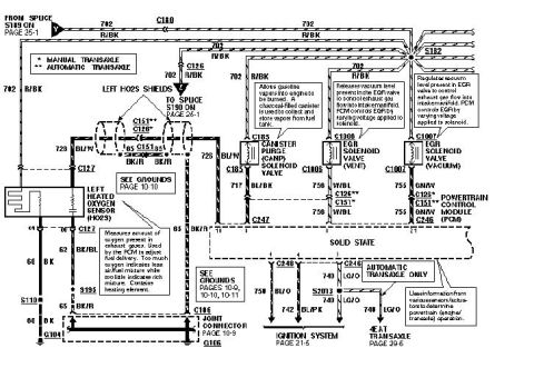
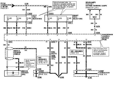
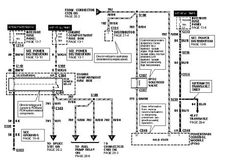
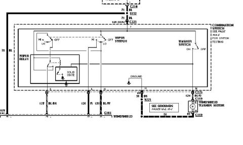
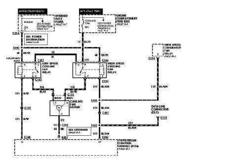









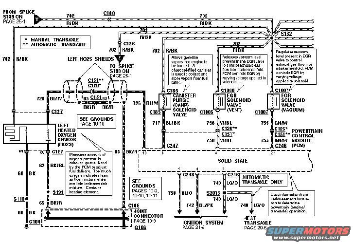
Ford wiring diagram showing the left HO2S, EGR and canister purge solenoid valves and PCM with color-coded wires and grounds.
Part of 1993-1997 Ford Probe Wiring Diagrams
This document is one page of a multi-page factory-style wiring diagram covering the Powertrain Control Module (PCM) circuits of a Ford Probe. It shows the left Heated Oxygen Sensor (HO2S) with its shield grounds, the Canister Purge (CANP) solenoid valve, and the two EGR solenoid valves (Vent, C1006, and Vacuum, C1007), all wired to the PCM (solid state module). Circuit numbers and wire colors are labeled throughout, e.g. 702 R/BK power feed from splice S189 (page 25-1), 728 BU/W and 726 BU/W to the HO2S and CANP valve, 717 BL/BK to PCM connector C247, 756 W/BL (EGR vent) and 755 GN/W (EGR vacuum) to PCM connector C246, plus grounds 60 BK, 62 BK/BL and 65 BK/R through splices S110/S195 to grounds G104 and G106 via joint connector C106. Connector callouts distinguish manual (C126*) versus automatic (C151**) transaxle. Explanatory notes describe how the HO2S, CANP and EGR solenoids operate. Cross-references point to grounds pages 10-9 through 10-11, the ignition system on page 21-5 (wires 750 BU/O, 742 BL/PK via C248), and the 4EAT automatic transaxle on page 29-5 (wire 740 LG/O via splice S2013).
Is this accurate? Sign in to help verify it.
Frequently asked questions
- What wire color feeds the left heated oxygen sensor and CANP solenoid power on this diagram?
- Circuit 702 R/BK (red/black) supplies power from splice S189 (page 25-1) through connector C180 and splice S182.
- Which PCM wires control the EGR solenoid valves?
- The EGR vent solenoid (C1006) uses circuit 756 W/BL and the EGR vacuum solenoid (C1007) uses circuit 755 GN/W, both routed through connector C126** or C151** to PCM connector C246.
- What is the difference between connectors marked with * and **?
- The legend states * = manual transaxle and ** = automatic transaxle; C126 is used on manual and C151 on automatic transaxle vehicles.
- How does the heated oxygen sensor work according to this diagram?
- It measures oxygen in the exhaust gases; the PCM uses it to adjust fuel delivery. Too much oxygen indicates a lean air/fuel mixture, too little indicates rich. It contains a heating element.
- Where do the HO2S ground circuits go?
- Grounds 60 BK, 62 BK/BL and 65 BK/R run through splices S110 and S195 to ground G104, and via joint connector C106 (page 10-9) to ground G106; see grounds pages 10-9, 10-10 and 10-11.






No comments yet.