Ford Probe PCM Wiring Diagram - VRIS, IAC Valve, HO2S & Power Steering Switch
Reference · 1993-1997 ProbeAll 65 wiring diagrams
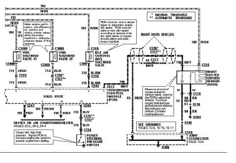
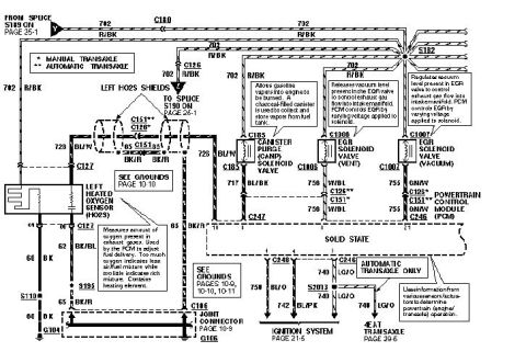
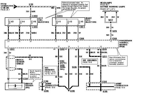
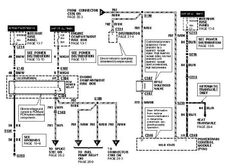









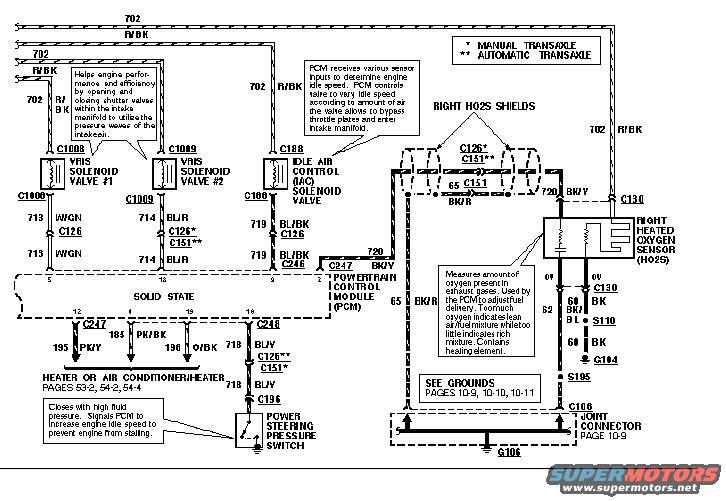
Ford wiring diagram showing the idle air control valve, VMS solenoid valves, right heated oxygen sensor and power steering pressure switch.
Part of 1993-1997 Ford Probe Wiring Diagrams
This is one page of a factory-style wiring diagram set (uploaded as "94 ecu page 4") covering the Powertrain Control Module (PCM) circuits for a Ford Probe. It shows the wiring for VRIS Solenoid Valve #1 (circuit 713 WGN via connector C1008/C1006), VRIS Solenoid Valve #2 (714 BL/R via C1009), the Idle Air Control (IAC) Solenoid Valve (719 BL/BK via C168/C100), the Right Heated Oxygen Sensor (720 BK/Y and 65 BK/R with shield connectors C126/C151 and grounds through S110, S195, G104, G106, and joint connector C106), and the Power Steering Pressure Switch (718 BU/Y via C196). All components receive power on circuit 702 R/BK. Asterisk footnotes distinguish manual (*) versus automatic (**) transaxle connector routing at C126 and C151. Explanatory callouts describe how the VRIS solenoids improve engine performance using intake pressure waves, how the PCM varies idle speed through the IAC valve, how the HO2S measures exhaust oxygen for fuel delivery adjustment, and how the power steering switch signals the PCM to raise idle under high fluid pressure. Cross-references point to grounds on pages 10-9 through 10-11 and heater/AC circuits on pages 53-2, 54-2, and 54-4.
Is this accurate? Sign in to help verify it.
Frequently asked questions
- What wire colors go to the VRIS solenoid valves?
- VRIS Solenoid Valve #1 uses circuit 713 WGN (through connector C126) and VRIS Solenoid Valve #2 uses circuit 714 BL/R (through C126* manual / C151** automatic). Both are fed by circuit 702 R/BK.
- What circuit does the Idle Air Control (IAC) solenoid valve use?
- The IAC solenoid valve (connector C168) is fed by 702 R/BK and controlled through circuit 719 BL/BK, which runs through C126 and C246 to the PCM.
- What does the power steering pressure switch do according to this diagram?
- It closes with high fluid pressure and signals the PCM to increase engine idle speed to prevent the engine from stalling. It connects via circuit 718 BU/Y through connectors C126**/C151* and C196.
- How is the right heated oxygen sensor wired?
- The Right HO2S receives 702 R/BK power for its heater, has signal circuit 720 BK/Y through C130, return 65 BK/R to the PCM, and grounds through 60 BK/BL (S110), 69 BK to G104, and circuit 62 through S195 to joint connector C106 and ground G106.
- What do the asterisks (*) and (**) mean on this diagram?
- A single asterisk (*) indicates manual transaxle and a double asterisk (**) indicates automatic transaxle, distinguishing which connector (C126 or C151) applies.






No comments yet.